
Video Port/VCXO Interpolated Control (VIC) Port User's Guide

www.ti.com
3.13.8 Video Capture Channel x Threshold Register (VCATHRLD, VCBTHRLD)
Video Capture Registers
The video capture channel x threshold register (VCATHRLD, VCBTHRLD) determines when EDMA
requests are sent.
The VCTHRLD1 bits determine when capture EDMA events are generated. Once the threshold is
reached, generation of further EDMA events is disabled until service of the previous event(s) begins (the
first FIFO read by the EDMA occurs).
In BT.656 and Y/C modes, every two captured pixels represent 2 luma values in the Y FIFO and 2 chroma
values (1 each in the Cb and Cr FIFOs). Depending on the data size each value may be a byte (8-bit
BT.656 or Y/C) within the FIFOs. Therefore, the VCTHRLD1 double word number represents 8 pixels in
8-bit modes. Since the Cb and Cr FIFO thresholds are represented by ½ VCTHRLD1, certain restrictions
are placed on what VCTHRLD1 values are valid (see Section 2.3.3 ).
In raw data mode, each data sample may occupy a byte (8-bit raw mode), 2bytes (16-bit raw mode),
within the FIFO, depending on the data size. Therefore, the VCTHRLD1 double word number represents 8
samples, 4 samples respectively.
In TCI mode, VCTHRLD1 represents groups of 8 samples with each sample occupying a byte in the FIFO.
The VCTHRLD2 bits behave identically to VCTHRLD1, but are used during field 2 capture. It is only used
if the field 2 EDMA size needs to be different from the field 1 EDMA size for some reason (for example,
different captured line lengths in field 1 and field 2). If VT2EN is not set, then the VCTHRLD1 value is
used for both fields.
Note that the VCTHRLD n applies to data being written into the FIFO. In the case of 8-bit BT.656 or Y/C
modes, this means the output of any selected filter.
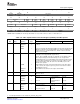
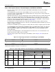
The video capture channel x threshold register (VC xTHRLD) is shown in Figure 3-28 and described in
Table 3-21 .
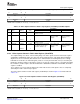
Figure 3-28. Video Capture Channel x Threshold Register (VC xTHRLD)
31 26 25 16
Reserved VCTHRLD2
R-0 R/W-0
15 10 9 0
Reserved VCTHRLD1
R-0 R/W-0
LEGEND: R/W = Read/Write; R = Read only; - n = value after reset
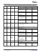
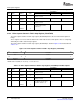
Table 3-21. Video Capture Channel x Threshold Register (VCxTHRLD) Field Descriptions
Description
Bit field
(1)
symval
(1)
Value BT.656 or Y/C Mode Raw Data Mode TCI Mode
31-26 Reserved - 0 Reserved. The reserved bit location is always read as 0. A value written to this
field has no effect.
25-16 VCTHRLD2 OF( value) 0-3FFh Number of field 2 double words Not used. Not used.
required to generate EDMA
events.
DEFAULT 0
15-10 Reserved - 0 Reserved. The reserved bit location is always read as 0. A value written to this
field has no effect.
9-0 VCTHRLD1 OF( value) 0-3FFh Number of field 1 double words Number of raw data Number of double
required to generate EDMA double words required words required to
events. to generate a EDMA generate a EDMA
event. event.
DEFAULT 0
(1)
For CSL implementation, use the notation VP_VC xTHRLD_VCTHRLD n_ symval
80 Video Capture Port SPRUEM1 – May 2007
Submit Documentation Feedback