
Video Port/VCXO Interpolated Control (VIC) Port User's Guide

www.ti.com
3.13.11 TCI Capture Control Register (TCICTL)
Video Capture Registers
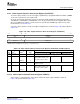
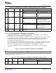
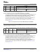
Table 3-23. Video Capture Channel B Control Register (VCBCTL) Field Descriptions (continued)
Description
Bit field
(1)
symval
(1)
Value BT.656 or Y/C Mode Raw Data Mode TCI Mode
4 CF1
(2)
OF( value) Capture field 1 bit.
NONE 0 Do not capture field 1. Not used. Not used.
DEFAULT 1 Capture field 1. Not used. Not used.
FLDCAP
3-2 Reserved - 0 Reserved. The reserved bit location is always read as 0. A value written to this field
has no effect.
1-0 CMODE OF( value) 0-3h Capture mode select bit.
DEFAULT 0 Enables 8-bit BT.656 mode. Not used.
BT656B
RAWB 2h Enables 8-bit raw data mode. Not used.
The ERRFILT, STEN, and TCKEN bits may be written at any time. To ensure stable counter operation,
writes to the CTMODE bit are disabled unless the system time counter is halted (ENSTC = 0).
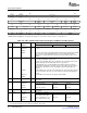
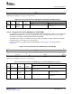
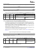
The transport stream interface capture control register (TCICTL) controls TCI capture operation. TCICTL
is shown in Figure 3-31 and described in Table 3-24 .
Figure 3-31. TCI Capture Control Register (TCICTL)
31 16
Reserved
R-0
15 6 5 4 3 2 1 0
Reserved ENSTC TCKEN STEN CTMODE ERRFILT Reserved
R-0 R/W-0 R/W-0 R/W-0 R/W-0 R/W-0 R/W-0
LEGEND: R/W = Read/Write; R = Read only; - n = value after reset
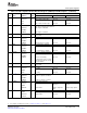
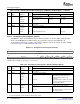
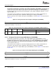
Table 3-24. TCI Capture Control Register (TCICTL) Field Descriptions
Description
Bit field
(1)
symval
(1)
Value BT.656, Y/C Mode, or Raw Data Mode TCI Mode
31-6 Reserved - 0 Reserved. The reserved bit location is always read as 0. A value written to this field
has no effect.
5 ENSTC OF( value) System time clock enable bit.
DEFAULT 0 Not used. System time clock input is disabled (to
save power). The system time clock
HALTED
counters and tick counter do not
increment.
CLKED 1 Not used. System time input is enabled. The system
time clock counters and tick counters are
incremented by STCLK.
4 TCKEN OF( value) Tick count interrupt enable bit.
DEFAULT 0 Not used. Setting of the TICK bit is disabled.
DISABLE
SET 1 Not used. The TICK bit in VPIS is set whenever the
tick count is reached.
(1)
For CSL implementation, use the notation VP_TCICTL_ field_ symval
84 Video Capture Port SPRUEM1 – May 2007
Submit Documentation Feedback