
Video Port/VCXO Interpolated Control (VIC) Port User's Guide

www.ti.com
4.1 Video Display Mode Selection
4.1.1 Image Timing
Line 20
Line 21
Line 22
Line 261
Line 262
Line 263
Line 282
Line 283
Line 284
Line 523
Line 524
Line 525
Field 1
Field 2
Video Display Mode Selection
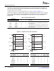
The video display module operates in one of three modes as listed in Table 4-1 . The DMODE bits are in
the video display control register (VDCTL). The Y/C and 16-bit raw display modes may only be selected if
the DCDIS bit in the video port control register (VPCTL) is cleared to 0.
Table 4-1. Video Display Mode Selection
DMODE Bits Mode Description
000 8-Bit ITU-R BT.656 Display Digital video output is in YCbCr 4:2:2 with 8-bit resolution multiplexed in ITU-R
BT.656 format.
010 8-Bit Raw Display 8-bit data output
100 8-Bit Y/C Display Digital video is output in YCbCr 4:2:2 with 8-bit resolution on parallel Y and
Cb/Cr multiplexed channels.
110 16-Bit Raw Display 16-bit data output.
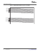
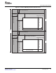
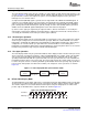
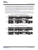
Display devices generate interlaced images by controlling the vertical retrace timing. The video display
module emits a data stream used to generate a displayed image. An NTSC-compatible interlaced image
with field and line information is shown in Figure 4-1 . A progressive-scan image (SMPTE 296M
compatible) is shown in Figure 4-2 .
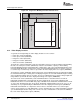
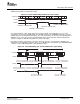
The active video area represents the pixels visible on the display. The active video area begins after the
horizontal and vertical blanking intervals. The image area output by the video display module can be a
subset of the active area. The relationship between frame, active video area, and image area is presented
in Figure 4-3 for interlaced video and in Figure 4-4 for progressive video. The video display module
generates timing for frames, active video areas within frames, and images within the active video area.
Figure 4-1. NTSC Compatible Interlaced Display
SPRUEM1 – May 2007 Video Display Port 93
Submit Documentation Feedback