TMS320F2809, TMS320F2808, TMS320F2806 TMS320F2802, TMS320F2801, TMS320C2802 TMS320C2801, TMS320F28016, TMS320F28015 Digital Signal Processors Data Manual PRODUCTION DATA information is current as of publication date. Products conform to specifications per the terms of the Texas Instruments standard warranty. Production processing does not necessarily include testing of all parameters.
TMS320F2809, TMS320F2808, TMS320F2806 TMS320F2802, TMS320F2801, TMS320C2802 TMS320C2801, TMS320F28016, TMS320F28015 www.ti.com SPRS230N – OCTOBER 2003 – REVISED MAY 2012 Contents 1 F280x, F2801x, C280x DSPs 1.1 1.2 2 Introduction 2.1 2.2 3 3.3 3.4 3.5 3.6 3.7 4 4.7 .......................................................................................................... 24 Memory Maps ..............................................................................................................
TMS320F2809, TMS320F2808, TMS320F2806 TMS320F2802, TMS320F2801, TMS320C2802 TMS320C2801, TMS320F28016, TMS320F28015 www.ti.com 4.8 4.9 4.10 4.11 5 6 7 8 9 SPRS230N – OCTOBER 2003 – REVISED MAY 2012 Serial Communications Interface (SCI) Modules (SCI-A, SCI-B) ................................................... Serial Peripheral Interface (SPI) Modules (SPI-A, SPI-B, SPI-C, SPI-D) .......................................... Inter-Integrated Circuit (I2C) ..................................................
TMS320F2809, TMS320F2808, TMS320F2806 TMS320F2802, TMS320F2801, TMS320C2802 TMS320C2801, TMS320F28016, TMS320F28015 SPRS230N – OCTOBER 2003 – REVISED MAY 2012 www.ti.com List of Figures ............................................................ 2-1 TMS320F2809, TMS320F2808 100-Pin PZ LQFP (Top View) 2-2 TMS320F2806 100-Pin PZ LQFP (Top View) ................................................................................
TMS320F2809, TMS320F2808, TMS320F2806 TMS320F2802, TMS320F2801, TMS320C2802 TMS320C2801, TMS320F28016, TMS320F28015 www.ti.com SPRS230N – OCTOBER 2003 – REVISED MAY 2012 6-9 Warm Reset ..................................................................................................................... 108 6-10 Example of Effect of Writing Into PLLCR Register ......................................................................... 109 6-11 General-Purpose Output Timing ...............................
TMS320F2809, TMS320F2808, TMS320F2806 TMS320F2802, TMS320F2801, TMS320C2802 TMS320C2801, TMS320F28016, TMS320F28015 SPRS230N – OCTOBER 2003 – REVISED MAY 2012 www.ti.com List of Tables 2-1 Hardware Features (100-MHz Devices) ....................................................................................... 11 2-2 Hardware Features (60-MHz Devices) ........................................................................................ 12 2-3 Signal Descriptions ..................................
TMS320F2809, TMS320F2808, TMS320F2806 TMS320F2802, TMS320F2801, TMS320C2802 TMS320C2801, TMS320F28016, TMS320F28015 www.ti.com 6-10 6-11 6-12 6-13 6-14 6-15 6-16 6-17 6-18 6-19 6-20 6-21 6-22 6-23 6-24 6-25 6-26 6-27 6-28 6-29 6-30 6-31 6-32 6-33 6-34 6-35 6-36 6-37 6-38 6-39 6-40 6-41 6-42 6-43 6-44 6-45 6-46 6-47 6-48 6-49 9-1 9-2 9-3 9-4 9-5 9-6 SPRS230N – OCTOBER 2003 – REVISED MAY 2012 ............................................................................. .....................................
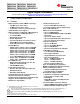
TMS320F2809, TMS320F2808, TMS320F2806 TMS320F2802, TMS320F2801, TMS320C2802 TMS320C2801, TMS320F28016, TMS320F28015 SPRS230N – OCTOBER 2003 – REVISED MAY 2012 www.ti.com Digital Signal Processors Check for Samples: TMS320F2809, TMS320F2808, TMS320F2806, TMS320F2802, TMS320F2801, TMS320C2802, TMS320C2801, TMS320F28016, TMS320F28015 1 F280x, F2801x, C280x DSPs 1.1 Features 1234 • High-Performance Static CMOS Technology – 100 MHz (10-ns Cycle Time) – 60 MHz (16.67-ns Cycle Time) – Low-Power (1.
TMS320F2809, TMS320F2808, TMS320F2806 TMS320F2802, TMS320F2801, TMS320C2802 TMS320C2801, TMS320F28016, TMS320F28015 www.ti.com • Package Options – Thin Quad Flatpack (PZ) – MicroStar BGA™ (GGM, ZGM) 1.2 SPRS230N – OCTOBER 2003 – REVISED MAY 2012 • Temperature Options – A: –40°C to 85°C (PZ, GGM, ZGM) – S: –40°C to 125°C (PZ, GGM, ZGM) – Q: –40°C to 125°C (PZ) Getting Started This section gives a brief overview of the steps to take when first developing for a C28x™ device.
TMS320F2809, TMS320F2808, TMS320F2806 TMS320F2802, TMS320F2801, TMS320C2802 TMS320C2801, TMS320F28016, TMS320F28015 SPRS230N – OCTOBER 2003 – REVISED MAY 2012 2 www.ti.com Introduction The TMS320F2809, TMS320F2808, TMS320F2806, TMS320F2802, TMS320F2801, TMS320F28015, TMS320F28016, TMS320C2802, and TMS320C2801 devices, members of the TMS320C28x™ DSP generation, are highly integrated, high-performance solutions for demanding control applications.
TMS320F2809, TMS320F2808, TMS320F2806 TMS320F2802, TMS320F2801, TMS320C2802 TMS320C2801, TMS320F28016, TMS320F28015 www.ti.com SPRS230N – OCTOBER 2003 – REVISED MAY 2012 Table 2-1.
TMS320F2809, TMS320F2808, TMS320F2806 TMS320F2802, TMS320F2801, TMS320C2802 TMS320C2801, TMS320F28016, TMS320F28015 SPRS230N – OCTOBER 2003 – REVISED MAY 2012 www.ti.com Table 2-2. Hardware Features (60-MHz Devices) TYPE (1) F2802-60 F2801-60 F28016 F28015 Instruction cycle (at 60 MHz) – 16.67 ns 16.67 ns 16.67 ns 16.67 ns Single-access RAM (SARAM) (16-bit word) – 6K (L0, M0, M1) 6K (L0, M0, M1) 6K (L0, M0, M1) 6K (L0, M0, M1) 3.
TMS320F2809, TMS320F2808, TMS320F2806 TMS320F2802, TMS320F2801, TMS320C2802 TMS320C2801, TMS320F28016, TMS320F28015 www.ti.com 2.
TMS320F2809, TMS320F2808, TMS320F2806 TMS320F2802, TMS320F2801, TMS320C2802 TMS320C2801, TMS320F28016, TMS320F28015 GPIO18/SPICLKA/SCITXDB GPIO5/EPWM3B/SPICLKD/ECAP1 GPIO17/SPISOMIA/TZ6 GPIO4/EPWM3A 54 53 52 51 GPIO6/EPWM4A/EPWMSYNCI/EPWMSYNCO VSS 56 55 GPIO7/EPWM4B/SPISTED/ECAP2 GPIO19/SPISTEA/SCIRXDB 57 59 58 GPIO9/EPWM5B/SCITXDB/ECAP3 GPIO8/EPWM5A/ADCSOCAO VDD 61 62 60 GPIO10/EPWM6A/ADCSOCBO GPIO20/EQEP1A/SPISIMOC VSS 64 63 XCLKOUT VDDIO 66 65 VDD GPIO21/EQEP1B/SPISOMIC 67 69 6
TMS320F2809, TMS320F2808, TMS320F2806 TMS320F2802, TMS320F2801, TMS320C2802 TMS320C2801, TMS320F28016, TMS320F28015 GPIO18/SPICLKA GPIO5/EPWM3B/ECAP1 GPIO17/SPISOMIA/TZ6 GPIO4/EPWM3A 54 53 52 51 GPIO6/EPWMSYNCI/EPWMSYNCO VSS 56 55 GPIO7/ECAP2 GPIO19/SPISTEA 57 59 58 GPIO9 GPIO8/ADCSOCAO VDD 61 62 60 GPIO10/ADCSOCBO GPIO20/EQEP1A VSS 64 63 XCLKOUT VDDIO 66 65 VDD GPIO21/EQEP1B 67 69 68 GPIO22/EQEP1S GPIO11 VSS 71 72 70 TMS 50 49 GPIO16/SPISIMOA/TZ5 VSS 78 48 GPIO3/EPWM2B
TMS320F2809, TMS320F2808, TMS320F2806 TMS320F2802, TMS320F2801, TMS320C2802 TMS320C2801, TMS320F28016, TMS320F28015 GPIO18/SPICLKA GPIO5/EPWM3B/ECAP1 GPIO17/SPISOMIA/TZ6 GPIO4/EPWM3A 54 53 52 51 GPIO6/EPWM4A/EPWMSYNCI/EPWMSYNCO VSS 56 55 GPIO7/EPWM4B/ECAP2 GPIO19/SPISTEA 57 59 58 GPIO9 GPIO8/ADCSOCAO VDD 61 62 60 GPIO10/ADCSOCBO GPIO20 VSS 64 63 XCLKOUT VDDIO 66 65 VDD GPIO21 67 69 68 GPIO22 GPIO11 VSS 71 72 70 TMS TDI GPIO23 50 49 GPIO16/SPISIMOA/TZ5 VSS 78 48 GPIO3/E
TMS320F2809, TMS320F2808, TMS320F2806 TMS320F2802, TMS320F2801, TMS320C2802 TMS320C2801, TMS320F28016, TMS320F28015 www.ti.
TMS320F2809, TMS320F2808, TMS320F2806 TMS320F2802, TMS320F2801, TMS320C2802 TMS320C2801, TMS320F28016, TMS320F28015 SPRS230N – OCTOBER 2003 – REVISED MAY 2012 2.2 www.ti.com Signal Descriptions Table 2-3 describes the signals on the 280x devices. All digital inputs are TTL-compatible. All outputs are 3.3 V with CMOS levels. Inputs are not 5-V tolerant. Table 2-3. Signal Descriptions PIN NO. NAME PZ PIN # GGM/ ZGM BALL # DESCRIPTION (1) JTAG TRST 84 A6 JTAG test reset with internal pulldown.
TMS320F2809, TMS320F2808, TMS320F2806 TMS320F2802, TMS320F2801, TMS320C2802 TMS320C2801, TMS320F28016, TMS320F28015 www.ti.com SPRS230N – OCTOBER 2003 – REVISED MAY 2012 Table 2-3. Signal Descriptions (continued) PIN NO. NAME PZ PIN # GGM/ ZGM BALL # DESCRIPTION (1) X1 88 E6 Internal/External Oscillator Input. To use the internal oscillator, a quartz crystal or a ceramic resonator may be connected across X1 and X2. The X1 pin is referenced to the 1.8-V core digital power supply. A 1.
TMS320F2809, TMS320F2808, TMS320F2806 TMS320F2802, TMS320F2801, TMS320C2802 TMS320C2801, TMS320F28016, TMS320F28015 SPRS230N – OCTOBER 2003 – REVISED MAY 2012 www.ti.com Table 2-3. Signal Descriptions (continued) PIN NO. NAME PZ PIN # GGM/ ZGM BALL # DESCRIPTION (1) CPU AND I/O POWER PINS VDDA2 15 F2 ADC Analog Power Pin (3.3 V) VSSA2 14 F1 ADC Analog Ground Pin VDDAIO 26 J2 ADC Analog I/O Power Pin (3.
TMS320F2809, TMS320F2808, TMS320F2806 TMS320F2802, TMS320F2801, TMS320C2802 TMS320C2801, TMS320F28016, TMS320F28015 www.ti.com SPRS230N – OCTOBER 2003 – REVISED MAY 2012 Table 2-3. Signal Descriptions (continued) PIN NO.
TMS320F2809, TMS320F2808, TMS320F2806 TMS320F2802, TMS320F2801, TMS320C2802 TMS320C2801, TMS320F28016, TMS320F28015 SPRS230N – OCTOBER 2003 – REVISED MAY 2012 www.ti.com Table 2-3. Signal Descriptions (continued) PIN NO.
TMS320F2809, TMS320F2808, TMS320F2806 TMS320F2802, TMS320F2801, TMS320C2802 TMS320C2801, TMS320F28016, TMS320F28015 www.ti.com SPRS230N – OCTOBER 2003 – REVISED MAY 2012 Table 2-3. Signal Descriptions (continued) PIN NO. NAME GPIO30 CANRXA - 6 GPIO31 CANTXA - 7 GPIO32 SDAA EPWMSYNCI ADCSOCAO GPIO33 SCLA EPWMSYNCO ADCSOCBO GPIO34 (1) PZ PIN # 100 5 43 GGM/ ZGM BALL # DESCRIPTION (1) D2 General-purpose input/output 30. This pin has an 8-mA (typical) output buffer.
TMS320F2809, TMS320F2808, TMS320F2806 TMS320F2802, TMS320F2801, TMS320C2802 TMS320C2801, TMS320F28016, TMS320F28015 SPRS230N – OCTOBER 2003 – REVISED MAY 2012 3 www.ti.
TMS320F2809, TMS320F2808, TMS320F2806 TMS320F2802, TMS320F2801, TMS320C2802 TMS320C2801, TMS320F28016, TMS320F28015 www.ti.com 3.
TMS320F2809, TMS320F2808, TMS320F2806 TMS320F2802, TMS320F2801, TMS320C2802 TMS320C2801, TMS320F28016, TMS320F28015 SPRS230N – OCTOBER 2003 – REVISED MAY 2012 www.ti.
TMS320F2809, TMS320F2808, TMS320F2806 TMS320F2802, TMS320F2801, TMS320C2802 TMS320C2801, TMS320F28016, TMS320F28015 www.ti.
TMS320F2809, TMS320F2808, TMS320F2806 TMS320F2802, TMS320F2801, TMS320C2802 TMS320C2801, TMS320F28016, TMS320F28015 SPRS230N – OCTOBER 2003 – REVISED MAY 2012 www.ti.
TMS320F2809, TMS320F2808, TMS320F2806 TMS320F2802, TMS320F2801, TMS320C2802 TMS320C2801, TMS320F28016, TMS320F28015 www.ti.
TMS320F2809, TMS320F2808, TMS320F2806 TMS320F2802, TMS320F2801, TMS320C2802 TMS320C2801, TMS320F28016, TMS320F28015 SPRS230N – OCTOBER 2003 – REVISED MAY 2012 www.ti.com Table 3-1.
TMS320F2809, TMS320F2808, TMS320F2806 TMS320F2802, TMS320F2801, TMS320C2802 TMS320C2801, TMS320F28016, TMS320F28015 www.ti.com SPRS230N – OCTOBER 2003 – REVISED MAY 2012 Table 3-4.
TMS320F2809, TMS320F2808, TMS320F2806 TMS320F2802, TMS320F2801, TMS320C2802 TMS320C2801, TMS320F28016, TMS320F28015 SPRS230N – OCTOBER 2003 – REVISED MAY 2012 www.ti.com The wait-states for the various spaces in the memory map area are listed in Table 3-6. Table 3-6. Wait-states 32 AREA WAIT-STATES COMMENTS M0 and M1 SARAMs 0-wait Fixed Peripheral Frame 0 0-wait Fixed Peripheral Frame 1 0-wait (writes) 2-wait (reads) Fixed. The eCAN peripheral can extend a cycle as needed.
TMS320F2809, TMS320F2808, TMS320F2806 TMS320F2802, TMS320F2801, TMS320C2802 TMS320C2801, TMS320F28016, TMS320F28015 www.ti.com 3.2 3.2.1 SPRS230N – OCTOBER 2003 – REVISED MAY 2012 Brief Descriptions C28x CPU The C28x™ DSP generation is the newest member of the TMS320C2000™ DSP platform. The C28x is a very efficient C/C++ engine, enabling users to develop not only their system control software in a highlevel language, but also enables math algorithms to be developed using C/C++.
TMS320F2809, TMS320F2808, TMS320F2806 TMS320F2802, TMS320F2801, TMS320C2802 TMS320C2801, TMS320F28016, TMS320F28015 SPRS230N – OCTOBER 2003 – REVISED MAY 2012 3.2.4 www.ti.com Real-Time JTAG and Analysis The 280x implements the standard IEEE 1149.1 JTAG interface. Additionally, the 280x supports real-time mode of operation whereby the contents of memory, peripheral and register locations can be modified while the processor is running and executing code and servicing interrupts.
TMS320F2809, TMS320F2808, TMS320F2806 TMS320F2802, TMS320F2801, TMS320C2802 TMS320C2801, TMS320F28016, TMS320F28015 www.ti.com 3.2.8 SPRS230N – OCTOBER 2003 – REVISED MAY 2012 L0, L1, H0 SARAMs The F2809 and F2808 each contain an additional 16K x 16 of single-access RAM, divided into three blocks (L0-4K, L1-4K, H0-8K). The F2806 contains an additional 8K x 16 of single-access RAM, divided into two blocks (L0-4K, L1-4K).
TMS320F2809, TMS320F2808, TMS320F2806 TMS320F2802, TMS320F2801, TMS320C2802 TMS320C2801, TMS320F28016, TMS320F28015 SPRS230N – OCTOBER 2003 – REVISED MAY 2012 www.ti.com 3.2.10 Security The 280x devices support high levels of security to protect the user firmware from being reverse engineered. The security features a 128-bit password (hardcoded for 16 wait-states), which the user programs into the flash. One code security module (CSM) is used to protect the flash/OTP and the L0/L1 SARAM blocks.
TMS320F2809, TMS320F2808, TMS320F2806 TMS320F2802, TMS320F2801, TMS320C2802 TMS320C2801, TMS320F28016, TMS320F28015 www.ti.com SPRS230N – OCTOBER 2003 – REVISED MAY 2012 3.2.11 Peripheral Interrupt Expansion (PIE) Block The PIE block serves to multiplex numerous interrupt sources into a smaller set of interrupt inputs. The PIE block can support up to 96 peripheral interrupts. On the 280x, 43 of the possible 96 interrupts are used by peripherals.
TMS320F2809, TMS320F2808, TMS320F2806 TMS320F2802, TMS320F2801, TMS320C2802 TMS320C2801, TMS320F28016, TMS320F28015 SPRS230N – OCTOBER 2003 – REVISED MAY 2012 www.ti.com 3.2.17 Peripheral Frames 0, 1, 2 (PFn) The 280x segregate peripherals into three sections.
TMS320F2809, TMS320F2808, TMS320F2806 TMS320F2802, TMS320F2801, TMS320C2802 TMS320C2801, TMS320F28016, TMS320F28015 www.ti.com SPRS230N – OCTOBER 2003 – REVISED MAY 2012 eQEP: The enhanced QEP peripheral uses a 32-bit position counter, supports low-speed measurement using capture unit and high-speed measurement using a 32-bit unit timer. This peripheral has a watchdog timer to detect motor stall and input error detection logic to identify simultaneous edge transition in QEP signals.
TMS320F2809, TMS320F2808, TMS320F2806 TMS320F2802, TMS320F2801, TMS320C2802 TMS320C2801, TMS320F28016, TMS320F28015 SPRS230N – OCTOBER 2003 – REVISED MAY 2012 www.ti.com Table 3-8.
TMS320F2809, TMS320F2808, TMS320F2806 TMS320F2802, TMS320F2801, TMS320C2802 TMS320C2801, TMS320F28016, TMS320F28015 www.ti.com SPRS230N – OCTOBER 2003 – REVISED MAY 2012 Table 3-10.
TMS320F2809, TMS320F2808, TMS320F2806 TMS320F2802, TMS320F2801, TMS320C2802 TMS320C2801, TMS320F28016, TMS320F28015 SPRS230N – OCTOBER 2003 – REVISED MAY 2012 www.ti.com When the PIE is enabled, TRAP #1 through TRAP #12 will transfer program control to the interrupt service routine corresponding to the first vector within the PIE group. For example: TRAP #1 fetches the vector from INT1.1, TRAP #2 fetches the vector from INT2.1 and so forth.
TMS320F2809, TMS320F2808, TMS320F2806 TMS320F2802, TMS320F2801, TMS320C2802 TMS320C2801, TMS320F28016, TMS320F28015 www.ti.com SPRS230N – OCTOBER 2003 – REVISED MAY 2012 IFR[12:1] IER[12:1] INTM INT1 INT2 1 MUX INT11 INT12 (Flag) INTx Global Enable (Enable) INTx.1 INTx.2 INTx.3 INTx.4 INTx.5 INTx.6 INTx.7 INTx.8 MUX PIEACKx (Enable/Flag) (Enable) (Flag) PIEIERx[8:1] PIEIFRx[8:1] CPU 0 From Peripherals or External Interrupts Figure 3-8.
TMS320F2809, TMS320F2808, TMS320F2806 TMS320F2802, TMS320F2801, TMS320C2802 TMS320C2801, TMS320F28016, TMS320F28015 SPRS230N – OCTOBER 2003 – REVISED MAY 2012 www.ti.com Table 3-13.
TMS320F2809, TMS320F2808, TMS320F2806 TMS320F2802, TMS320F2801, TMS320C2802 TMS320C2801, TMS320F28016, TMS320F28015 www.ti.com SPRS230N – OCTOBER 2003 – REVISED MAY 2012 Each external interrupt can be enabled/disabled or qualified using positive, negative, or both positive and negative edge. For more information, see the TMS320x280x, 2801x, 2804x DSP System Control and Interrupts Reference Guide (literature number SPRU712). 3.
TMS320F2809, TMS320F2808, TMS320F2806 TMS320F2802, TMS320F2801, TMS320C2802 TMS320C2801, TMS320F28016, TMS320F28015 SPRS230N – OCTOBER 2003 – REVISED MAY 2012 www.ti.com The PLL, clocking, watchdog and low-power modes, are controlled by the registers listed in Table 3-15. Table 3-15.
TMS320F2809, TMS320F2808, TMS320F2806 TMS320F2802, TMS320F2801, TMS320C2802 TMS320C2801, TMS320F28016, TMS320F28015 www.ti.com SPRS230N – OCTOBER 2003 – REVISED MAY 2012 The three possible input-clock configurations are shown in Figure 3-11 through Figure 3-13. XCLKIN X1 X2 NC External Clock Signal (Toggling 0-VDDIO) Figure 3-11. Using a 3.3-V External Oscillator XCLKIN X1 X2 External Clock Signal (Toggling 0-VDD) NC Figure 3-12. Using a 1.
TMS320F2809, TMS320F2808, TMS320F2806 TMS320F2802, TMS320F2801, TMS320C2802 TMS320C2801, TMS320F28016, TMS320F28015 SPRS230N – OCTOBER 2003 – REVISED MAY 2012 3.6.1.2 www.ti.com PLL-Based Clock Module The 280x devices have an on-chip, PLL-based clock module. This module provides all the necessary clocking signals for the device, as well as control for low-power mode entry. The PLL has a 4-bit ratio control PLLCR[DIV] to select different CPU clock rates.
TMS320F2809, TMS320F2808, TMS320F2806 TMS320F2802, TMS320F2801, TMS320C2802 TMS320C2801, TMS320F28016, TMS320F28015 www.ti.com SPRS230N – OCTOBER 2003 – REVISED MAY 2012 Table 3-17. Possible PLL Configuration Modes REMARKS PLLSTS[CLKINDIV] SYSCLKOUT (CLKIN) 0 OSCCLK/2 PLL Off Invoked by the user setting the PLLOFF bit in the PLLSTS register. The PLL block is disabled in this mode. This can be useful to reduce system noise and for low power operation.
TMS320F2809, TMS320F2808, TMS320F2806 TMS320F2802, TMS320F2801, TMS320C2802 TMS320C2801, TMS320F28016, TMS320F28015 SPRS230N – OCTOBER 2003 – REVISED MAY 2012 3.6.2 www.ti.com Watchdog Block The watchdog block on the 280x is similar to the one used on the 240x and 281x devices. The watchdog module generates an output pulse, 512 oscillator clocks wide (OSCCLK), whenever the 8-bit watchdog up counter has reached its maximum value.
TMS320F2809, TMS320F2808, TMS320F2806 TMS320F2802, TMS320F2801, TMS320C2802 TMS320C2801, TMS320F28016, TMS320F28015 www.ti.com 3.7 SPRS230N – OCTOBER 2003 – REVISED MAY 2012 Low-Power Modes Block The low-power modes on the 280x are similar to the 240x devices. Table 3-18 summarizes the various modes. Table 3-18.
TMS320F2809, TMS320F2808, TMS320F2806 TMS320F2802, TMS320F2801, TMS320C2802 TMS320C2801, TMS320F28016, TMS320F28015 SPRS230N – OCTOBER 2003 – REVISED MAY 2012 4 www.ti.
TMS320F2809, TMS320F2808, TMS320F2806 TMS320F2802, TMS320F2801, TMS320C2802 TMS320C2801, TMS320F28016, TMS320F28015 www.ti.com SPRS230N – OCTOBER 2003 – REVISED MAY 2012 In the 280x devices, the timer interrupt signals (TINT0, TINT1, TINT2) are connected as shown in Figure 4-2. INT1 to INT12 TINT0 PIE CPU-TIMER 0 C28x TINT1 INT13 CPU-TIMER 1 XINT13 CPU-TIMER 2 (Reserved for DSP/BIOS) TINT2 INT14 A. B. The timer registers are connected to the memory bus of the C28x processor.
TMS320F2809, TMS320F2808, TMS320F2806 TMS320F2802, TMS320F2801, TMS320C2802 TMS320C2801, TMS320F28016, TMS320F28015 SPRS230N – OCTOBER 2003 – REVISED MAY 2012 www.ti.com Table 4-1. CPU-Timers 0, 1, 2 Configuration and Control Registers (continued) ADDRESS SIZE (x16) Reserved NAME 0x0C15 1 Reserved TIMER2TPR 0x0C16 1 CPU-Timer 2, Prescale Register TIMER2TPRH 0x0C17 1 CPU-Timer 2, Prescale Register High 0x0C18 – 0x0C3F 40 Reserved Reserved 4.
TMS320F2809, TMS320F2808, TMS320F2806 TMS320F2802, TMS320F2801, TMS320C2802 TMS320C2801, TMS320F28016, TMS320F28015 www.ti.com SPRS230N – OCTOBER 2003 – REVISED MAY 2012 Table 4-2.
TMS320F2809, TMS320F2808, TMS320F2806 TMS320F2802, TMS320F2801, TMS320C2802 TMS320C2801, TMS320F28016, TMS320F28015 SPRS230N – OCTOBER 2003 – REVISED MAY 2012 www.ti.
TMS320F2809, TMS320F2808, TMS320F2806 TMS320F2802, TMS320F2801, TMS320C2802 TMS320C2801, TMS320F28016, TMS320F28015 www.ti.com 4.3 SPRS230N – OCTOBER 2003 – REVISED MAY 2012 Hi-Resolution PWM (HRPWM) The HRPWM module offers PWM resolution (time granularity) which is significantly better than what can be achieved using conventionally derived digital PWM methods.
TMS320F2809, TMS320F2808, TMS320F2806 TMS320F2802, TMS320F2801, TMS320C2802 TMS320C2801, TMS320F28016, TMS320F28015 SPRS230N – OCTOBER 2003 – REVISED MAY 2012 www.ti.
TMS320F2809, TMS320F2808, TMS320F2806 TMS320F2802, TMS320F2801, TMS320C2802 TMS320C2801, TMS320F28016, TMS320F28015 www.ti.com SPRS230N – OCTOBER 2003 – REVISED MAY 2012 Table 4-3.
TMS320F2809, TMS320F2808, TMS320F2806 TMS320F2802, TMS320F2801, TMS320C2802 TMS320C2801, TMS320F28016, TMS320F28015 SPRS230N – OCTOBER 2003 – REVISED MAY 2012 4.5 www.ti.com Enhanced QEP Modules (eQEP1/2) The 280x device contains up to two enhanced quadrature encoder (eQEP) modules. See the TMS320x280x, 2801x, 2804x Enhanced Quadrature Encoder Pulse (eQEP) Module Reference Guide (literature number SPRU790) for more details.
TMS320F2809, TMS320F2808, TMS320F2806 TMS320F2802, TMS320F2801, TMS320C2802 TMS320C2801, TMS320F28016, TMS320F28015 www.ti.com SPRS230N – OCTOBER 2003 – REVISED MAY 2012 Table 4-4.
TMS320F2809, TMS320F2808, TMS320F2806 TMS320F2802, TMS320F2801, TMS320C2802 TMS320C2801, TMS320F28016, TMS320F28015 SPRS230N – OCTOBER 2003 – REVISED MAY 2012 4.6 www.ti.com Enhanced Analog-to-Digital Converter (ADC) Module A simplified functional block diagram of the ADC module is shown in Figure 4-7. The ADC module consists of a 12-bit ADC with a built-in sample-and-hold (S/H) circuit. Functions of the ADC module include: • 12-bit ADC core with built-in S/H • Analog input: 0.0 V to 3.
TMS320F2809, TMS320F2808, TMS320F2806 TMS320F2802, TMS320F2801, TMS320C2802 TMS320C2801, TMS320F28016, TMS320F28015 www.ti.
TMS320F2809, TMS320F2808, TMS320F2806 TMS320F2802, TMS320F2801, TMS320C2802 TMS320C2801, TMS320F28016, TMS320F28015 SPRS230N – OCTOBER 2003 – REVISED MAY 2012 www.ti.com Figure 4-8 shows the ADC pin-biasing for internal reference and Figure 4-9 shows the ADC pin-biasing for external reference.
TMS320F2809, TMS320F2808, TMS320F2806 TMS320F2802, TMS320F2801, TMS320C2802 TMS320C2801, TMS320F28016, TMS320F28015 www.ti.com SPRS230N – OCTOBER 2003 – REVISED MAY 2012 ADC 16-Channel Analog Inputs ADC External Current Bias Resistor ADCRESEXT ADC Reference Positive Output ADCREFP ADC Reference Medium Output ADCREFM ADC Analog Power ADC Analog and Reference I/O Power A. B. C. D.
TMS320F2809, TMS320F2808, TMS320F2806 TMS320F2802, TMS320F2801, TMS320C2802 TMS320C2801, TMS320F28016, TMS320F28015 SPRS230N – OCTOBER 2003 – REVISED MAY 2012 4.6.2 www.ti.com ADC Registers The ADC operation is configured, controlled, and monitored by the registers listed in Table 4-5. Table 4-5.
TMS320F2809, TMS320F2808, TMS320F2806 TMS320F2802, TMS320F2801, TMS320C2802 TMS320C2801, TMS320F28016, TMS320F28015 www.ti.com 4.7 SPRS230N – OCTOBER 2003 – REVISED MAY 2012 Enhanced Controller Area Network (eCAN) Modules (eCAN-A and eCAN-B) The CAN module has the following features: • Fully compliant with CAN protocol, version 2.
TMS320F2809, TMS320F2808, TMS320F2806 TMS320F2802, TMS320F2801, TMS320C2802 TMS320C2801, TMS320F28016, TMS320F28015 SPRS230N – OCTOBER 2003 – REVISED MAY 2012 eCAN0INT www.ti.
TMS320F2809, TMS320F2808, TMS320F2806 TMS320F2802, TMS320F2801, TMS320C2802 TMS320C2801, TMS320F28016, TMS320F28015 www.ti.
TMS320F2809, TMS320F2808, TMS320F2806 TMS320F2802, TMS320F2801, TMS320C2802 TMS320C2801, TMS320F28016, TMS320F28015 SPRS230N – OCTOBER 2003 – REVISED MAY 2012 www.ti.
TMS320F2809, TMS320F2808, TMS320F2806 TMS320F2802, TMS320F2801, TMS320C2802 TMS320C2801, TMS320F28016, TMS320F28015 www.ti.com SPRS230N – OCTOBER 2003 – REVISED MAY 2012 The CAN registers listed in Table 4-7 are used by the CPU to configure and control the CAN controller and the message objects. eCAN control registers only support 32-bit read/write operations. Mailbox RAM can be accessed as 16 bits or 32 bits. 32-bit accesses are aligned to an even boundary. Table 4-7.
TMS320F2809, TMS320F2808, TMS320F2806 TMS320F2802, TMS320F2801, TMS320C2802 TMS320C2801, TMS320F28016, TMS320F28015 SPRS230N – OCTOBER 2003 – REVISED MAY 2012 4.8 www.ti.com Serial Communications Interface (SCI) Modules (SCI-A, SCI-B) The 280x devices include two serial communications interface (SCI) modules. The SCI modules support digital communications between the CPU and other asynchronous peripherals that use the standard nonreturn-to-zero (NRZ) format.
TMS320F2809, TMS320F2808, TMS320F2806 TMS320F2802, TMS320F2801, TMS320C2802 TMS320C2801, TMS320F28016, TMS320F28015 www.ti.com SPRS230N – OCTOBER 2003 – REVISED MAY 2012 Enhanced features: • Auto baud-detect hardware logic • 16-level transmit/receive FIFO The SCI port operation is configured and controlled by the registers listed in Table 4-8 and Table 4-9. Table 4-8.
TMS320F2809, TMS320F2808, TMS320F2806 TMS320F2802, TMS320F2801, TMS320C2802 TMS320C2801, TMS320F28016, TMS320F28015 SPRS230N – OCTOBER 2003 – REVISED MAY 2012 www.ti.com Figure 4-13 shows the SCI module block diagram. SCICTL1.1 Frame Format and Mode SCITXD TXSHF Register Parity Even/Odd Enable TX EMPTY SCICTL2.6 8 SCICCR.6 SCICCR.5 TXRDY SCICTL2.7 Transmitter-Data Buffer Register TXWAKE SCICTL1.3 WUT SCICTL2.
TMS320F2809, TMS320F2808, TMS320F2806 TMS320F2802, TMS320F2801, TMS320C2802 TMS320C2801, TMS320F28016, TMS320F28015 www.ti.com 4.9 SPRS230N – OCTOBER 2003 – REVISED MAY 2012 Serial Peripheral Interface (SPI) Modules (SPI-A, SPI-B, SPI-C, SPI-D) The 280x devices include the four-pin serial peripheral interface (SPI) module. Up to four SPI modules (SPI-A, SPI-B, SPI-C, and SPI-D) are available.
TMS320F2809, TMS320F2808, TMS320F2806 TMS320F2802, TMS320F2801, TMS320C2802 TMS320C2801, TMS320F28016, TMS320F28015 SPRS230N – OCTOBER 2003 – REVISED MAY 2012 www.ti.com The SPI port operation is configured and controlled by the registers listed in Table 4-10 through Table 413. Table 4-10.
TMS320F2809, TMS320F2808, TMS320F2806 TMS320F2802, TMS320F2801, TMS320C2802 TMS320C2801, TMS320F28016, TMS320F28015 www.ti.com SPRS230N – OCTOBER 2003 – REVISED MAY 2012 Table 4-12.
TMS320F2809, TMS320F2808, TMS320F2806 TMS320F2802, TMS320F2801, TMS320C2802 TMS320C2801, TMS320F28016, TMS320F28015 SPRS230N – OCTOBER 2003 – REVISED MAY 2012 www.ti.com Figure 4-14 is a block diagram of the SPI in slave mode. SPIFFENA SPIFFTX.14 Overrun INT ENA Receiver Overrun Flag RX FIFO Registers SPIRXBUF RX FIFO _0 RX FIFO _1 ----RX FIFO _15 SPISTS.7 SPICTL.4 RX FIFO Interrupt RX Interrupt Logic 16 SPIINT/SPIRXINT SPIFFOVF FLAG SPIRXBUF Buffer Register To CPU SPIFFRX.
TMS320F2809, TMS320F2808, TMS320F2806 TMS320F2802, TMS320F2801, TMS320C2802 TMS320C2801, TMS320F28016, TMS320F28015 www.ti.com SPRS230N – OCTOBER 2003 – REVISED MAY 2012 4.10 Inter-Integrated Circuit (I2C) The 280x device contains one I2C Serial Port. Figure 4-15 shows how the I2C peripheral module interfaces within the 280x device. The I2C module has the following features: • Compliance with the Philips Semiconductors I2C-bus specification (version 2.
TMS320F2809, TMS320F2808, TMS320F2806 TMS320F2802, TMS320F2801, TMS320C2802 TMS320C2801, TMS320F28016, TMS320F28015 SPRS230N – OCTOBER 2003 – REVISED MAY 2012 www.ti.com System Control Block C28x CPU I2CAENCLK SYSRS Control Data[16] SDAA GPIO MUX Peripheral Bus SYSCLKOUT Data[16] I2C-A Addr[16] SCLA I2CINT1A I2CINT2A A. B. PIE Block The I2C registers are accessed at the SYSCLKOUT rate. The internal timing and signal waveforms of the I2C port are also at the SYSCLKOUT rate.
TMS320F2809, TMS320F2808, TMS320F2806 TMS320F2802, TMS320F2801, TMS320C2802 TMS320C2801, TMS320F28016, TMS320F28015 www.ti.com SPRS230N – OCTOBER 2003 – REVISED MAY 2012 4.11 GPIO MUX On the 280x, the GPIO MUX can multiplex up to three independent peripheral signals on a single GPIO pin in addition to providing individual pin bit-banging IO capability. The GPIO MUX block diagram per pin is shown in Figure 4-16.
TMS320F2809, TMS320F2808, TMS320F2806 TMS320F2802, TMS320F2801, TMS320C2802 TMS320C2801, TMS320F28016, TMS320F28015 SPRS230N – OCTOBER 2003 – REVISED MAY 2012 www.ti.com The 280x supports 34 GPIO pins. The GPIO control and data registers are mapped to Peripheral Frame 1 to enable 32-bit operations on the registers (along with 16-bit operations). Table 4-15 shows the GPIO register mapping. Table 4-15.
TMS320F2809, TMS320F2808, TMS320F2806 TMS320F2802, TMS320F2801, TMS320C2802 TMS320C2801, TMS320F28016, TMS320F28015 www.ti.com SPRS230N – OCTOBER 2003 – REVISED MAY 2012 Table 4-16.
TMS320F2809, TMS320F2808, TMS320F2806 TMS320F2802, TMS320F2801, TMS320C2802 TMS320C2801, TMS320F28016, TMS320F28015 SPRS230N – OCTOBER 2003 – REVISED MAY 2012 www.ti.com The user can select the type of input qualification for each GPIO pin via the GPxQSEL1/2 registers from four choices: • Synchronization To SYSCLKOUT Only (GPxQSEL1/2 = 0,0): This is the default mode of all GPIO pins at reset and it simply synchronizes the input signal to the system clock (SYSCLKOUT).
TMS320F2809, TMS320F2808, TMS320F2806 TMS320F2802, TMS320F2801, TMS320C2802 TMS320C2801, TMS320F28016, TMS320F28015 www.ti.com 5 SPRS230N – OCTOBER 2003 – REVISED MAY 2012 Device Support Texas Instruments (TI) offers an extensive line of development tools for the C28x™ generation of DSPs, including tools to evaluate the performance of the processors, generate code, develop algorithm implementations, and fully integrate and debug software and hardware modules.
TMS320F2809, TMS320F2808, TMS320F2806 TMS320F2802, TMS320F2801, TMS320C2802 TMS320C2801, TMS320F28016, TMS320F28015 SPRS230N – OCTOBER 2003 – REVISED MAY 2012 www.ti.com Predictions show that prototype devices (TMX or TMP) have a greater failure rate than the standard production devices. Texas Instruments recommends that these devices not be used in any production system because their expected end-use failure rate still is undefined. Only qualified production devices are to be used.
TMS320F2809, TMS320F2808, TMS320F2806 TMS320F2802, TMS320F2801, TMS320C2802 TMS320C2801, TMS320F28016, TMS320F28015 www.ti.com 5.2 SPRS230N – OCTOBER 2003 – REVISED MAY 2012 Documentation Support Extensive documentation supports all of the TMS320™ DSP family generations of devices from product announcement through applications development. The types of documentation available include: data sheets and data manuals, with design specifications; and hardware and software applications.
TMS320F2809, TMS320F2808, TMS320F2806 TMS320F2802, TMS320F2801, TMS320C2802 TMS320C2801, TMS320F28016, TMS320F28015 SPRS230N – OCTOBER 2003 – REVISED MAY 2012 www.ti.com Peripheral Guides SPRU566 TMS320x28xx, 28xxx DSP Peripheral Reference Guide describes the peripheral reference guides of the 28x digital signal processors (DSPs).
TMS320F2809, TMS320F2808, TMS320F2806 TMS320F2802, TMS320F2801, TMS320C2802 TMS320C2801, TMS320F28016, TMS320F28015 www.ti.com SPRS230N – OCTOBER 2003 – REVISED MAY 2012 Application Reports and Software Key Links Include: 1. C2000 Get Started - www.ti.com/c2000getstarted 2. C2000 Digital Motor Control Software Library - www.ti.com/c2000appsw 3. C2000 Digital Power Supply Software Library - www.ti.com/dpslib 4. DSP Power Management Reference Designs - www.ti.
TMS320F2809, TMS320F2808, TMS320F2806 TMS320F2802, TMS320F2801, TMS320C2802 TMS320C2801, TMS320F28016, TMS320F28015 SPRS230N – OCTOBER 2003 – REVISED MAY 2012 www.ti.com SPRAAD8 TMS320x280x and TMS320F2801x ADC Calibration describes a method for improving the absolute accuracy of the 12-bit ADC found on the TMS320x280x and TMS320F2801x devices. Inherent gain and offset errors affect the absolute accuracy of the ADC.
TMS320F2809, TMS320F2808, TMS320F2806 TMS320F2802, TMS320F2801, TMS320C2802 TMS320C2801, TMS320F28016, TMS320F28015 www.ti.
TMS320F2809, TMS320F2808, TMS320F2806 TMS320F2802, TMS320F2801, TMS320C2802 TMS320C2801, TMS320F28016, TMS320F28015 SPRS230N – OCTOBER 2003 – REVISED MAY 2012 5.3 www.ti.com Community Resources The following links connect to TI community resources. Linked contents are provided "AS IS" by the respective contributors. They do not constitute TI specifications and do not necessarily reflect TI's views; see TI's Terms of Use. TI E2E Community TI's Engineer-to-Engineer (E2E) Community.
TMS320F2809, TMS320F2808, TMS320F2806 TMS320F2802, TMS320F2801, TMS320C2802 TMS320C2801, TMS320F28016, TMS320F28015 www.ti.com 6 SPRS230N – OCTOBER 2003 – REVISED MAY 2012 Electrical Specifications This section provides the absolute maximum ratings and the recommended operating conditions for the TMS320F280x DSPs. 6.1 Absolute Maximum Ratings (1) (2) Unless otherwise noted, the list of absolute maximum ratings are specified over operating temperature ranges.
TMS320F2809, TMS320F2808, TMS320F2806 TMS320F2802, TMS320F2801, TMS320C2802 TMS320C2801, TMS320F28016, TMS320F28015 SPRS230N – OCTOBER 2003 – REVISED MAY 2012 6.2 www.ti.com Recommended Operating Conditions over operating free-air temperature range (unless otherwise noted) MIN NOM MAX UNIT Device supply voltage, I/O, VDDIO 3.14 3.3 3.47 V Device supply voltage CPU, VDD 1.71 1.8 1.89 V Supply ground, VSS, VSSIO 0 V ADC supply voltage (3.3 V), VDDA2, VDDAIO 3.14 3.3 3.
TMS320F2809, TMS320F2808, TMS320F2806 TMS320F2802, TMS320F2801, TMS320C2802 TMS320C2801, TMS320F28016, TMS320F28015 www.ti.com 6.4 SPRS230N – OCTOBER 2003 – REVISED MAY 2012 Current Consumption Table 6-1.
TMS320F2809, TMS320F2808, TMS320F2806 TMS320F2802, TMS320F2801, TMS320C2802 TMS320C2801, TMS320F28016, TMS320F28015 SPRS230N – OCTOBER 2003 – REVISED MAY 2012 www.ti.com Table 6-2.
TMS320F2809, TMS320F2808, TMS320F2806 TMS320F2802, TMS320F2801, TMS320C2802 TMS320C2801, TMS320F28016, TMS320F28015 www.ti.com SPRS230N – OCTOBER 2003 – REVISED MAY 2012 Table 6-3.
TMS320F2809, TMS320F2808, TMS320F2806 TMS320F2802, TMS320F2801, TMS320C2802 TMS320C2801, TMS320F28016, TMS320F28015 SPRS230N – OCTOBER 2003 – REVISED MAY 2012 www.ti.com Table 6-4.
TMS320F2809, TMS320F2808, TMS320F2806 TMS320F2802, TMS320F2801, TMS320C2802 TMS320C2801, TMS320F28016, TMS320F28015 www.ti.com 6.4.1 SPRS230N – OCTOBER 2003 – REVISED MAY 2012 Reducing Current Consumption 280x devices have a richer peripheral mix compared to the 281x family.
TMS320F2809, TMS320F2808, TMS320F2806 TMS320F2802, TMS320F2801, TMS320C2802 TMS320C2801, TMS320F28016, TMS320F28015 SPRS230N – OCTOBER 2003 – REVISED MAY 2012 6.4.2 www.ti.com Current Consumption Graphs 250.0 Current (mA) 200.0 150.0 100.0 50.0 0.0 10 20 30 40 50 60 70 80 90 100 SYSCLKOUT (MHz) IDD IDDA18 1.8-V current IDDIO IDD3VFL 3.3-V current Figure 6-1. Typical Operational Current Versus Frequency (F2808) 600.0 500.0 Device Power (mW) 400.0 300.0 200.0 100.0 0.
TMS320F2809, TMS320F2808, TMS320F2806 TMS320F2802, TMS320F2801, TMS320C2802 TMS320C2801, TMS320F28016, TMS320F28015 www.ti.com SPRS230N – OCTOBER 2003 – REVISED MAY 2012 Current Vs SYSCLKOUT 200 180 Current (mA) 160 140 120 100 80 60 40 20 0 10 20 30 40 50 60 70 80 90 10 SYSCLKOUT (MHz) IDD IDDA18 1.8v current IDDIO IDD3VFL 3.3v current Figure 6-3. Typical Operational Current Versus Frequency (C280x) Device Power (mW) Device Power Vs SYSCLKOUT 400.0 300.0 200.0 100.0 0.
TMS320F2809, TMS320F2808, TMS320F2806 TMS320F2802, TMS320F2801, TMS320C2802 TMS320C2801, TMS320F28016, TMS320F28015 SPRS230N – OCTOBER 2003 – REVISED MAY 2012 6.5 www.ti.com Emulator Connection Without Signal Buffering for the DSP Figure 6-5 shows the connection between the DSP and JTAG header for a single-processor configuration. If the distance between the JTAG header and the DSP is greater than 6 inches, the emulation signals must be buffered.
TMS320F2809, TMS320F2808, TMS320F2806 TMS320F2802, TMS320F2801, TMS320C2802 TMS320C2801, TMS320F28016, TMS320F28015 www.ti.com 6.6 SPRS230N – OCTOBER 2003 – REVISED MAY 2012 Timing Parameter Symbology Timing parameter symbols used are created in accordance with JEDEC Standard 100. To shorten the symbols, some of the pin names and other related terminology have been abbreviated as follows: 6.6.
TMS320F2809, TMS320F2808, TMS320F2806 TMS320F2802, TMS320F2801, TMS320C2802 TMS320C2801, TMS320F28016, TMS320F28015 SPRS230N – OCTOBER 2003 – REVISED MAY 2012 6.6.3 www.ti.com Device Clock Table This section provides the timing requirements and switching characteristics for the various clock options available on the 280x DSPs. Table 6-6 and Table 6-7 list the cycle times of various clocks. Table 6-6.
TMS320F2809, TMS320F2808, TMS320F2806 TMS320F2802, TMS320F2801, TMS320C2802 TMS320C2801, TMS320F28016, TMS320F28015 www.ti.com 6.7 SPRS230N – OCTOBER 2003 – REVISED MAY 2012 Clock Requirements and Characteristics Table 6-8.
TMS320F2809, TMS320F2808, TMS320F2806 TMS320F2802, TMS320F2801, TMS320C2802 TMS320C2801, TMS320F28016, TMS320F28015 SPRS230N – OCTOBER 2003 – REVISED MAY 2012 www.ti.com C10 C9 C8 XCLKIN(A) C6 C3 C1 C4 C5 XCLKOUT(B) A. B. The relationship of XCLKIN to XCLKOUT depends on the divide factor chosen. The waveform relationship shown is intended to illustrate the timing parameters only and may differ based on actual configuration. XCLKOUT configured to reflect SYSCLKOUT. Figure 6-7. Clock Timing 6.
TMS320F2809, TMS320F2808, TMS320F2806 TMS320F2802, TMS320F2801, TMS320C2802 TMS320C2801, TMS320F28016, TMS320F28015 www.ti.com SPRS230N – OCTOBER 2003 – REVISED MAY 2012 VDDIO, VDD3VFL VDDA2, VDDAIO (3.3 V) VDD, VDD1A18, VDD2A18 (1.8 V) XCLKIN X1/X2 OSCCLK/8(A) XCLKOUT User-Code Dependent tOSCST tw(RSL1) XRS Address/Data Valid.
TMS320F2809, TMS320F2808, TMS320F2806 TMS320F2802, TMS320F2801, TMS320C2802 TMS320C2801, TMS320F28016, TMS320F28015 SPRS230N – OCTOBER 2003 – REVISED MAY 2012 www.ti.com Table 6-13.
TMS320F2809, TMS320F2808, TMS320F2806 TMS320F2802, TMS320F2801, TMS320C2802 TMS320C2801, TMS320F28016, TMS320F28015 www.ti.com SPRS230N – OCTOBER 2003 – REVISED MAY 2012 Figure 6-10 shows an example for the effect of writing into PLLCR register. In the first phase, PLLCR = 0x0004 and SYSCLKOUT = OSCCLK x 2. The PLLCR is then written with 0x0008. Right after the PLLCR register is written, the PLL lock-up phase begins. During this phase, SYSCLKOUT = OSCCLK/2.
TMS320F2809, TMS320F2808, TMS320F2806 TMS320F2802, TMS320F2801, TMS320C2802 TMS320C2801, TMS320F28016, TMS320F28015 SPRS230N – OCTOBER 2003 – REVISED MAY 2012 6.9.2 www.ti.com GPIO - Input Timing (A) GPIO Signal GPxQSELn = 1,0 (6 samples) 1 1 0 0 0 0 0 0 0 1 0 tw(SP) 0 0 1 1 1 1 1 1 1 1 1 Sampling Period determined by GPxCTRL[QUALPRD](B) tw(IQSW) (SYSCLKOUT cycle * 2 * QUALPRD) * 5(C)) Sampling Window SYSCLKOUT QUALPRD = 1 (SYSCLKOUT/2) (D) Output From Qualifier A. B. C. D.
TMS320F2809, TMS320F2808, TMS320F2806 TMS320F2802, TMS320F2801, TMS320C2802 TMS320C2801, TMS320F28016, TMS320F28015 www.ti.com 6.9.3 SPRS230N – OCTOBER 2003 – REVISED MAY 2012 Sampling Window Width for Input Signals The following section summarizes the sampling window width for input signals for various input qualifier configurations. Sampling frequency denotes how often a signal is sampled with respect to SYSCLKOUT.
TMS320F2809, TMS320F2808, TMS320F2806 TMS320F2802, TMS320F2801, TMS320C2802 TMS320C2801, TMS320F28016, TMS320F28015 SPRS230N – OCTOBER 2003 – REVISED MAY 2012 6.9.4 www.ti.com Low-Power Mode Wakeup Timing Table 6-16 shows the timing requirements, Table 6-17 shows the switching characteristics, and Figure 614 shows the timing diagram for IDLE mode. Table 6-16.
TMS320F2809, TMS320F2808, TMS320F2806 TMS320F2802, TMS320F2801, TMS320C2802 TMS320C2801, TMS320F28016, TMS320F28015 www.ti.com SPRS230N – OCTOBER 2003 – REVISED MAY 2012 Table 6-18. STANDBY Mode Timing Requirements tw(WAKE-INT) (1) Pulse duration, external wake-up signal TEST CONDITIONS MIN Without input qualification 3tc(OSCCLK) With input qualification (1) NOM MAX UNIT cycles (2 + QUALSTDBY) * tc(OSCCLK) QUALSTDBY is a 6-bit field in the LPMCR0 register. Table 6-19.
TMS320F2809, TMS320F2808, TMS320F2806 TMS320F2802, TMS320F2801, TMS320C2802 TMS320C2801, TMS320F28016, TMS320F28015 SPRS230N – OCTOBER 2003 – REVISED MAY 2012 www.ti.com Table 6-20. HALT Mode Timing Requirements MIN tw(WAKE-GPIO) Pulse duration, GPIO wake-up signal tw(WAKE-XRS) Pulse duration, XRS wakeup signal (1) NOM MAX UNIT (1) cycles toscst + 8tc(OSCCLK) cycles toscst + 2tc(OSCCLK) See Table 6-13 for an explanation of toscst. Table 6-21.
TMS320F2809, TMS320F2808, TMS320F2806 TMS320F2802, TMS320F2801, TMS320C2802 TMS320C2801, TMS320F28016, TMS320F28015 www.ti.com SPRS230N – OCTOBER 2003 – REVISED MAY 2012 6.10 Enhanced Control Peripherals 6.10.1 Enhanced Pulse Width Modulator (ePWM) Timing PWM refers to PWM outputs on ePWM1–6. Table 6-22 shows the PWM timing requirements and Table 623, switching characteristics. Table 6-22.
TMS320F2809, TMS320F2808, TMS320F2806 TMS320F2802, TMS320F2801, TMS320C2802 TMS320C2801, TMS320F28016, TMS320F28015 SPRS230N – OCTOBER 2003 – REVISED MAY 2012 www.ti.com Table 6-25 shows the high-resolution PWM switching characteristics. Table 6-25. High-Resolution PWM Characteristics at SYSCLKOUT = 60–100 MHz MIN Micro Edge Positioning (MEP) step size (1) TYP MAX UNIT 150 310 ps (1) Maximum MEP step size is based on worst-case process, maximum temperature and maximum voltage.
TMS320F2809, TMS320F2808, TMS320F2806 TMS320F2802, TMS320F2801, TMS320C2802 TMS320C2801, TMS320F28016, TMS320F28015 www.ti.com SPRS230N – OCTOBER 2003 – REVISED MAY 2012 Table 6-30. External ADC Start-of-Conversion Switching Characteristics PARAMETER tw(ADCSOCAL) MIN Pulse duration, ADCSOCAO low MAX 32tc(HCO ) UNIT cycles tw(ADCSOCAL) ADCSOCAO or ADCSOCBO Figure 6-18. ADCSOCAO or ADCSOCBO Timing 6.10.
TMS320F2809, TMS320F2808, TMS320F2806 TMS320F2802, TMS320F2801, TMS320C2802 TMS320C2801, TMS320F28016, TMS320F28015 SPRS230N – OCTOBER 2003 – REVISED MAY 2012 www.ti.com 6.10.4 I2C Electrical Specification and Timing Table 6-33.
TMS320F2809, TMS320F2808, TMS320F2806 TMS320F2802, TMS320F2801, TMS320C2802 TMS320C2801, TMS320F28016, TMS320F28015 www.ti.com SPRS230N – OCTOBER 2003 – REVISED MAY 2012 Table 6-34. SPI Master Mode External Timing (Clock Phase = 0) (1) SPI WHEN (SPIBRR + 1) IS EVEN OR SPIBRR = 0 OR 2 NO.
TMS320F2809, TMS320F2808, TMS320F2806 TMS320F2802, TMS320F2801, TMS320C2802 TMS320C2801, TMS320F28016, TMS320F28015 SPRS230N – OCTOBER 2003 – REVISED MAY 2012 www.ti.com 1 SPICLK (clock polarity = 0) 2 3 SPICLK (clock polarity = 1) 4 5 SPISIMO Master Out Data Is Valid 8 9 SPISOMI Master In Data Must Be Valid SPISTE(A) A. In the master mode, SPISTE goes active 0.5tc(SPC) (minimum) before valid SPI clock edge. On the trailing end of the word, the SPISTE will go inactive 0.
TMS320F2809, TMS320F2808, TMS320F2806 TMS320F2802, TMS320F2801, TMS320C2802 TMS320C2801, TMS320F28016, TMS320F28015 www.ti.com SPRS230N – OCTOBER 2003 – REVISED MAY 2012 Table 6-35. SPI Master Mode External Timing (Clock Phase = 1) (1) SPI WHEN (SPIBRR + 1) IS EVEN OR SPIBRR = 0 OR 2 NO.
TMS320F2809, TMS320F2808, TMS320F2806 TMS320F2802, TMS320F2801, TMS320C2802 TMS320C2801, TMS320F28016, TMS320F28015 SPRS230N – OCTOBER 2003 – REVISED MAY 2012 www.ti.com 1 SPICLK (clock polarity = 0) 2 3 SPICLK (clock polarity = 1) 6 7 SPISIMO Master Out Data Is Valid Data Valid 10 11 SPISOMI Master In Data Must Be Valid SPISTE(A) A. In the master mode, SPISTE goes active 0.5tc(SPC) (minimum) before valid SPI clock edge. On the trailing end of the word, the SPISTE will go inactive 0.
TMS320F2809, TMS320F2808, TMS320F2806 TMS320F2802, TMS320F2801, TMS320C2802 TMS320C2801, TMS320F28016, TMS320F28015 www.ti.com SPRS230N – OCTOBER 2003 – REVISED MAY 2012 6.10.6 SPI Slave Mode Timing Table 6-36 lists the slave mode external timing (clock phase = 0) and Table 6-37 (clock phase = 1). Figure 6-22 and Figure 6-23 show the timing waveforms. Table 6-36. SPI Slave Mode External Timing (Clock Phase = 0) (1) (2) (3) (4) (5) NO.
TMS320F2809, TMS320F2808, TMS320F2806 TMS320F2802, TMS320F2801, TMS320C2802 TMS320C2801, TMS320F28016, TMS320F28015 SPRS230N – OCTOBER 2003 – REVISED MAY 2012 www.ti.com Table 6-37. SPI Slave Mode External Timing (Clock Phase = 1) (1) NO. 12 13 14 17 18 21 22 (1) (2) (3) (4) (2) (3) (4) MIN MAX tc(SPC)S Cycle time, SPICLK 8tc(LCO) tw(SPCH)S Pulse duration, SPICLK high (clock polarity = 0) 0.5tc(SPC)S – 10 0.5tc(SPC)S tw(SPCL)S Pulse duration, SPICLK low (clock polarity = 1) 0.
TMS320F2809, TMS320F2808, TMS320F2806 TMS320F2802, TMS320F2801, TMS320C2802 TMS320C2801, TMS320F28016, TMS320F28015 www.ti.com SPRS230N – OCTOBER 2003 – REVISED MAY 2012 6.10.7 On-Chip Analog-to-Digital Converter Table 6-38. ADC Electrical Characteristics (over recommended operating conditions) (1) (2) PARAMETER MIN TYP MAX UNIT MHz DC SPECIFICATIONS Resolution 12 ADC clock Bits 60-MHz device 0.001 7.5 100-MHz device 0.001 12.5 100-MHz device (F2809 only) 0.
TMS320F2809, TMS320F2808, TMS320F2806 TMS320F2802, TMS320F2801, TMS320C2802 TMS320C2801, TMS320F28016, TMS320F28015 SPRS230N – OCTOBER 2003 – REVISED MAY 2012 www.ti.com 6.10.7.1 ADC Power-Up Control Bit Timing ADC Power Up Delay ADC Ready for Conversions PWDNBG PWDNREF td(BGR) PWDNADC td(PWD) Request for ADC Conversion Figure 6-24. ADC Power-Up Control Bit Timing Table 6-39. ADC Power-Up Delays PARAMETER (1) MIN td(BGR) Delay time for band gap reference to be stable.
TMS320F2809, TMS320F2808, TMS320F2806 TMS320F2802, TMS320F2801, TMS320C2802 TMS320C2801, TMS320F28016, TMS320F28015 www.ti.com SPRS230N – OCTOBER 2003 – REVISED MAY 2012 Rs Source Signal ADCIN0 Ron 1 kΩ Switch Cp 10 pF ac Ch 1.64 pF 28x DSP Typical Values of the Input Circuit Components: Switch Resistance (Ron): Sampling Capacitor (Ch): Parasitic Capacitance (Cp): Source Resistance (Rs): 1 kΩ 1.64 pF 10 pF 50 Ω Figure 6-25. ADC Analog Input Impedance Model 6.10.7.
TMS320F2809, TMS320F2808, TMS320F2806 TMS320F2802, TMS320F2801, TMS320C2802 TMS320C2801, TMS320F28016, TMS320F28015 SPRS230N – OCTOBER 2003 – REVISED MAY 2012 www.ti.com 6.10.7.3 Sequential Sampling Mode (Single-Channel) (SMODE = 0) In sequential sampling mode, the ADC can continuously convert input signals on any of the channels (Ax to Bx). The ADC can start conversions on event triggers from the ePWM, software trigger, or from an external ADCSOC signal.
TMS320F2809, TMS320F2808, TMS320F2806 TMS320F2802, TMS320F2801, TMS320C2802 TMS320C2801, TMS320F28016, TMS320F28015 www.ti.com SPRS230N – OCTOBER 2003 – REVISED MAY 2012 6.10.7.4 Simultaneous Sampling Mode (Dual-Channel) (SMODE = 1) In simultaneous mode, the ADC can continuously convert input signals on any one pair of channels (A0/B0 to A7/B7). The ADC can start conversions on event triggers from the ePWM, software trigger, or from an external ADCSOC signal.
TMS320F2809, TMS320F2808, TMS320F2806 TMS320F2802, TMS320F2801, TMS320C2802 TMS320C2801, TMS320F28016, TMS320F28015 SPRS230N – OCTOBER 2003 – REVISED MAY 2012 www.ti.com 6.11 Detailed Descriptions Integral Nonlinearity Integral nonlinearity refers to the deviation of each individual code from a line drawn from zero through full scale. The point used as zero occurs one-half LSB before the first code transition. The full-scale point is defined as level one-half LSB beyond the last code transition.
TMS320F2809, TMS320F2808, TMS320F2806 TMS320F2802, TMS320F2801, TMS320C2802 TMS320C2801, TMS320F28016, TMS320F28015 www.ti.com SPRS230N – OCTOBER 2003 – REVISED MAY 2012 6.12 Flash Timing Table 6-43.
TMS320F2809, TMS320F2808, TMS320F2806 TMS320F2802, TMS320F2801, TMS320C2802 TMS320C2801, TMS320F28016, TMS320F28015 SPRS230N – OCTOBER 2003 – REVISED MAY 2012 www.ti.com Table 6-46.
TMS320F2809, TMS320F2808, TMS320F2806 TMS320F2802, TMS320F2801, TMS320C2802 TMS320C2801, TMS320F28016, TMS320F28015 www.ti.com SPRS230N – OCTOBER 2003 – REVISED MAY 2012 6.13 ROM Timing (C280x only) Table 6-48. ROM/OTP Access Timing PARAMETER MIN TYP MAX UNIT ta(rp) Paged ROM access time 19 ns ta(rr) Random ROM access time 19 ns ta(ROM) ROM (OTP area) access time 60 ns (1) (1) In C280x devices, a 1K X 16 ROM block replaces the OTP block found in Flash devices.
TMS320F2809, TMS320F2808, TMS320F2806 TMS320F2802, TMS320F2801, TMS320C2802 TMS320C2801, TMS320F28016, TMS320F28015 SPRS230N – OCTOBER 2003 – REVISED MAY 2012 7 Migrating From F280x Devices to C280x Devices 7.1 Migration Issues www.ti.com The migration issues to be considered while migrating from the F280x devices to C280x devices are as follows: • The 1K OTP memory available in F280x devices has been replaced by 1K ROM C280x devices.
TMS320F2809, TMS320F2808, TMS320F2806 TMS320F2802, TMS320F2801, TMS320C2802 TMS320C2801, TMS320F28016, TMS320F28015 www.ti.com 8 SPRS230N – OCTOBER 2003 – REVISED MAY 2012 Revision History This data sheet revision history highlights the technical changes made to the SPRS230M device-specific data sheet to make it an SPRS230N revision. Scope: See table below. LOCATION ADDITIONS, DELETIONS, AND MODIFICATIONS Section 1.1 Features: • Added "Endianness: Little Endian" feature Section 5.
TMS320F2809, TMS320F2808, TMS320F2806 TMS320F2802, TMS320F2801, TMS320C2802 TMS320C2801, TMS320F28016, TMS320F28015 SPRS230N – OCTOBER 2003 – REVISED MAY 2012 9 www.ti.com Mechanical Data Table 9-1 through Table 9-6 show the thermal data. The mechanical package diagram(s) that follow the table(s) reflect the most current released mechanical data available for the designated device(s). Table 9-1.
TMS320F2809, TMS320F2808, TMS320F2806 TMS320F2802, TMS320F2801, TMS320C2802 TMS320C2801, TMS320F28016, TMS320F28015 www.ti.com SPRS230N – OCTOBER 2003 – REVISED MAY 2012 Table 9-6. F2809 Thermal Model 100-pin PZ Results AIR FLOW PARAMETER 0 lfm 150 lfm 250 lfm 500 lfm θJA[°C/W] High k PCB 44.02 28.34 36.28 33.68 ΨJT[°C/W] 0.2 0.56 0.7 0.95 θJC 7.06 θJB 28.
PACKAGE OPTION ADDENDUM www.ti.
PACKAGE OPTION ADDENDUM www.ti.
PACKAGE OPTION ADDENDUM www.ti.
PACKAGE OPTION ADDENDUM www.ti.
PACKAGE OPTION ADDENDUM www.ti.com (4) 30-Oct-2013 There may be additional marking, which relates to the logo, the lot trace code information, or the environmental category on the device. (5) Multiple Device Markings will be inside parentheses. Only one Device Marking contained in parentheses and separated by a "~" will appear on a device. If a line is indented then it is a continuation of the previous line and the two combined represent the entire Device Marking for that device.
MECHANICAL DATA MPBG028B FEBRUARY 1997 – REVISED MAY 2002 GGM (S–PBGA–N100) PLASTIC BALL GRID ARRAY 10,10 SQ 9,90 7,20 TYP 0,80 0,40 K 0,80 J H G F E 0,40 D C B A A1 Corner 1 2 3 4 5 6 7 8 9 10 Bottom View 0,95 0,85 1,40 MAX Seating Plane 0,55 0,45 0,08 0,45 0,35 0,10 4145257–3/C 12/01 NOTES: A. All linear dimensions are in millimeters. B. This drawing is subject to change without notice C. MicroStar BGA configuration.
MECHANICAL DATA MTQF013A – OCTOBER 1994 – REVISED DECEMBER 1996 PZ (S-PQFP-G100) PLASTIC QUAD FLATPACK 0,27 0,17 0,50 75 0,08 M 51 76 50 100 26 1 0,13 NOM 25 12,00 TYP Gage Plane 14,20 SQ 13,80 16,20 SQ 15,80 0,05 MIN 1,45 1,35 0,25 0°– 7° 0,75 0,45 Seating Plane 0,08 1,60 MAX 4040149 /B 11/96 NOTES: A. All linear dimensions are in millimeters. B. This drawing is subject to change without notice. C.
IMPORTANT NOTICE Texas Instruments Incorporated and its subsidiaries (TI) reserve the right to make corrections, enhancements, improvements and other changes to its semiconductor products and services per JESD46, latest issue, and to discontinue any product or service per JESD48, latest issue. Buyers should obtain the latest relevant information before placing orders and should verify that such information is current and complete.