TMS320F2810, TMS320F2811, TMS320F2812 TMS320C2810, TMS320C2811, TMS320C2812 Digital Signal Processors Data Manual PRODUCTION DATA information is current as of publication date. Products conform to specifications per the terms of the Texas Instruments standard warranty. Production processing does not necessarily include testing of all parameters.
TMS320F2810, TMS320F2811, TMS320F2812 TMS320C2810, TMS320C2811, TMS320C2812 www.ti.com SPRS174T – APRIL 2001 – REVISED MAY 2012 Contents 1 TMS320F281x, TMS320C281x DSPs 1.1 1.2 2 Introduction 2.1 2.2 2.3 2.4 3 ...................................................................................................................... 12 Description ................................................................................................................. Device Summary ..............................
TMS320F2810, TMS320F2811, TMS320F2812 TMS320C2810, TMS320C2811, TMS320C2812 www.ti.com 4.1 4.2 4.3 4.4 4.5 4.6 4.7 4.8 5 32-Bit CPU-Timers 0/1/2 ................................................................................................. Event Manager Modules (EVA, EVB) ................................................................................... 4.2.1 General-Purpose (GP) Timers ................................................................................ 4.2.2 Full-Compare Units ........
TMS320F2810, TMS320F2811, TMS320F2812 TMS320C2810, TMS320C2811, TMS320C2812 SPRS174T – APRIL 2001 – REVISED MAY 2012 6.28 6.29 6.30 6.31 6.32 6.33 6.34 www.ti.com XHOLD and XHOLDA ................................................................................................... XHOLD/XHOLDA Timing ............................................................................................... On-Chip Analog-to-Digital Converter ...........................................................................
TMS320F2810, TMS320F2811, TMS320F2812 TMS320C2810, TMS320C2811, TMS320C2812 www.ti.com SPRS174T – APRIL 2001 – REVISED MAY 2012 List of Figures 2-1 TMS320F2812 and TMS320C2812 179-Ball GHH/ZHH MicroStar BGA™ (Bottom View).............................
TMS320F2810, TMS320F2811, TMS320F2812 TMS320C2810, TMS320C2811, TMS320C2812 SPRS174T – APRIL 2001 – REVISED MAY 2012 www.ti.com 6-21 EVBSOC Timing ................................................................................................................ 113 6-22 External Interrupt Timing ....................................................................................................... 114 6-23 General-Purpose Output Timing ...................................................................
TMS320F2810, TMS320F2811, TMS320F2812 TMS320C2810, TMS320C2811, TMS320C2812 www.ti.com SPRS174T – APRIL 2001 – REVISED MAY 2012 List of Tables 2-1 Hardware Features ............................................................................................................... 13 2-2 Signal Descriptions ...............................................................................................................
TMS320F2810, TMS320F2811, TMS320F2812 TMS320C2810, TMS320C2811, TMS320C2812 SPRS174T – APRIL 2001 – REVISED MAY 2012 6-13 6-14 6-15 6-16 6-17 6-18 6-19 6-20 6-21 6-22 6-23 6-24 6-25 6-26 6-27 6-28 6-29 6-30 6-31 6-32 6-33 6-34 6-35 6-36 6-37 6-38 6-39 6-40 6-41 6-42 6-43 6-44 6-45 6-46 6-47 6-48 6-49 6-50 6-51 6-52 6-53 6-54 6-55 6-56 6-57 6-58 6-59 6-60 8 www.ti.com ....................................................................................... ...................................................
TMS320F2810, TMS320F2811, TMS320F2812 TMS320C2810, TMS320C2811, TMS320C2812 www.ti.com SPRS174T – APRIL 2001 – REVISED MAY 2012 6-61 Flash Endurance for Q Temperature Material .............................................................................. 157 6-62 Flash Parameters at 150-MHz SYSCLKOUT ............................................................................... 157 6-63 Flash/OTP Access Timing ..........................................................................................
TMS320F2810, TMS320F2811, TMS320F2812 TMS320C2810, TMS320C2811, TMS320C2812 SPRS174T – APRIL 2001 – REVISED MAY 2012 www.ti.com Digital Signal Processors Check for Samples: TMS320F2810, TMS320F2811, TMS320F2812, TMS320C2810, TMS320C2811, TMS320C2812 1 TMS320F281x, TMS320C281x DSPs 1.1 Features 1234 • High-Performance Static CMOS Technology – 150 MHz (6.67-ns Cycle Time) – Low-Power (1.8-V Core at 135 MHz, 1.9-V Core at 150 MHz, 3.
TMS320F2810, TMS320F2811, TMS320F2812 TMS320C2810, TMS320C2811, TMS320C2812 www.ti.com • Package Options – 179-Ball MicroStar BGA™ With External Memory Interface (GHH, ZHH) (2812) – 176-Pin Low-Profile Quad Flatpack (LQFP) With External Memory Interface (PGF) (2812) – 128-Pin LQFP Without External Memory Interface (PBK) (2810, 2811) 1.
TMS320F2810, TMS320F2811, TMS320F2812 TMS320C2810, TMS320C2811, TMS320C2812 SPRS174T – APRIL 2001 – REVISED MAY 2012 2 www.ti.com Introduction This section provides a summary of each device’s features, lists the pin assignments, and describes the function of each pin. This document also provides detailed descriptions of peripherals, electrical specifications, parameter measurement information, and mechanical data about the available packaging. 2.
TMS320F2810, TMS320F2811, TMS320F2812 TMS320C2810, TMS320C2811, TMS320C2812 www.ti.com 2.2 SPRS174T – APRIL 2001 – REVISED MAY 2012 Device Summary Table 2-1 provides a summary of each device’s features. Table 2-1. Hardware Features (1) TYPE (2) F2810 F2811 F2812 C2810 C2811 C2812 Instruction Cycle (at 150 MHz) – 6.67 ns 6.67 ns 6.67 ns 6.67 ns 6.67 ns 6.67 ns Single-Access RAM (SARAM) (16-bit word) – 18K 18K 18K 18K 18K 18K 3.
TMS320F2810, TMS320F2811, TMS320F2812 TMS320C2810, TMS320C2811, TMS320C2812 SPRS174T – APRIL 2001 – REVISED MAY 2012 2.3 www.ti.com Pin Assignments Figure 2-1 illustrates the ball locations for the 179-ball GHH and ZHH ball grid array (BGA) packages. Figure 2-2 shows the pin assignments for the 176-pin PGF low-profile quad flatpack (LQFP) and Figure 23 shows the pin assignments for the 128-pin PBK LQFP. Table 2-2 describes the function(s) of each pin. 2.3.
TMS320F2810, TMS320F2811, TMS320F2812 TMS320C2810, TMS320C2811, TMS320C2812 www.ti.com 2.3.
TMS320F2810, TMS320F2811, TMS320F2812 TMS320C2810, TMS320C2811, TMS320C2812 SPRS174T – APRIL 2001 – REVISED MAY 2012 2.3.3 www.ti.
TMS320F2810, TMS320F2811, TMS320F2812 TMS320C2810, TMS320C2811, TMS320C2812 www.ti.com 2.4 SPRS174T – APRIL 2001 – REVISED MAY 2012 Signal Descriptions Table 2-2 specifies the signals on the F281x and C281x devices. All digital inputs are TTL-compatible. All outputs are 3.3 V with CMOS levels. Inputs are not 5-V tolerant. A 100-µA (or 20-µA) pullup/pulldown is used. Table 2-2. Signal Descriptions (1) PIN NO.
TMS320F2810, TMS320F2811, TMS320F2812 TMS320C2810, TMS320C2811, TMS320C2812 SPRS174T – APRIL 2001 – REVISED MAY 2012 www.ti.com Table 2-2. Signal Descriptions(1) (continued) PIN NO. NAME XMP/MC 179-BALL GHH/ZHH F1 XHOLD E7 176-PIN PGF 17 159 128-PIN PBK – – I/O/Z (2) I I PU/PD (3) DESCRIPTION PD Microprocessor/Microcomputer Mode Select. Switches between microprocessor and microcomputer mode. When high, Zone 7 is enabled on the external interface.
TMS320F2810, TMS320F2811, TMS320F2812 TMS320C2810, TMS320C2811, TMS320C2812 www.ti.com SPRS174T – APRIL 2001 – REVISED MAY 2012 Table 2-2. Signal Descriptions(1) (continued) PIN NO. NAME 179-BALL GHH/ZHH 176-PIN PGF 128-PIN PBK I/O/Z (2) PU/PD (3) DESCRIPTION JTAG AND MISCELLANEOUS SIGNALS X1/XCLKIN K9 77 58 I – Oscillator Input – input to the internal oscillator. This pin is also used to feed an external clock.
TMS320F2810, TMS320F2811, TMS320F2812 TMS320C2810, TMS320C2811, TMS320C2812 SPRS174T – APRIL 2001 – REVISED MAY 2012 www.ti.com Table 2-2. Signal Descriptions(1) (continued) PIN NO. NAME 179-BALL GHH/ZHH 176-PIN PGF 128-PIN PBK I/O/Z (2) PU/PD (3) DESCRIPTION JTAG JTAG test reset with internal pulldown. TRST, when driven high, gives the scan system control of the operations of the device.
TMS320F2810, TMS320F2811, TMS320F2812 TMS320C2810, TMS320C2811, TMS320C2812 www.ti.com SPRS174T – APRIL 2001 – REVISED MAY 2012 Table 2-2. Signal Descriptions(1) (continued) PIN NO. NAME 179-BALL GHH/ZHH 176-PIN PGF 128-PIN PBK I/O/Z (2) PU/PD (3) DESCRIPTION Emulator pin 1. When TRST is driven high, this pin is used as an interrupt to or from the emulator system and is defined as input/output through the JTAG scan. This pin is also used to put the device into boundary-scan mode.
TMS320F2810, TMS320F2811, TMS320F2812 TMS320C2810, TMS320C2811, TMS320C2812 SPRS174T – APRIL 2001 – REVISED MAY 2012 www.ti.com Table 2-2. Signal Descriptions(1) (continued) PIN NO. NAME 179-BALL GHH/ZHH 176-PIN PGF 128-PIN PBK I/O/Z (2) PU/PD (3) DESCRIPTION ADC External Current Bias Resistor. Use 24.9 kΩ ± 5% for ADC clock range 1–18.75 MHz; use 20 kΩ ± 5% for ADC clock range 18.75 MHz–25 MHz. ADCRESEXT F2 16 16 O – ADCBGREFIN E6 164 116 – – Test Pin. Reserved for TI.
TMS320F2810, TMS320F2811, TMS320F2812 TMS320C2810, TMS320C2811, TMS320C2812 www.ti.com SPRS174T – APRIL 2001 – REVISED MAY 2012 Table 2-2. Signal Descriptions(1) (continued) PIN NO. 179-BALL GHH/ZHH 176-PIN PGF 128-PIN PBK I/O/Z (2) PU/PD (3) VDDIO J4 31 25 – – VDDIO L7 64 49 – – VDDIO L10 81 – – – VDDIO N14 – – – – VDDIO G11 114 83 – – VDDIO E9 145 104 – – NAME VDD3VFL N8 69 52 – – DESCRIPTION 3 3-V I/O Digital Power Pins 3.3-V Flash Core Power Pin.
TMS320F2810, TMS320F2811, TMS320F2812 TMS320C2810, TMS320C2811, TMS320C2812 SPRS174T – APRIL 2001 – REVISED MAY 2012 www.ti.com Table 2-2. Signal Descriptions(1) (continued) PIN NO.
TMS320F2810, TMS320F2811, TMS320F2812 TMS320C2810, TMS320C2811, TMS320C2812 www.ti.com SPRS174T – APRIL 2001 – REVISED MAY 2012 Table 2-2. Signal Descriptions(1) (continued) PIN NO. NAME 179-BALL GHH/ZHH 176-PIN PGF 128-PIN PBK I/O/Z (2) PU/PD (3) DESCRIPTION GPIOF OR XF CPU OUTPUT SIGNAL GPIOF14 XF_XPLLDIS (O) A11 140 101 I/O PU This pin has three functions: 1. XF – General-purpose output pin. 2. XPLLDIS – This pin is sampled during reset to check whether the PLL must be disabled.
TMS320F2810, TMS320F2811, TMS320F2812 TMS320C2810, TMS320C2811, TMS320C2812 SPRS174T – APRIL 2001 – REVISED MAY 2012 3 www.ti.
TMS320F2810, TMS320F2811, TMS320F2812 TMS320C2810, TMS320C2811, TMS320C2812 www.ti.com 3.
TMS320F2810, TMS320F2811, TMS320F2812 TMS320C2810, TMS320C2811, TMS320C2812 SPRS174T – APRIL 2001 – REVISED MAY 2012 www.ti.
TMS320F2810, TMS320F2811, TMS320F2812 TMS320C2810, TMS320C2811, TMS320C2812 www.ti.
TMS320F2810, TMS320F2811, TMS320F2812 TMS320C2810, TMS320C2811, TMS320C2812 SPRS174T – APRIL 2001 – REVISED MAY 2012 www.ti.com Table 3-1.
TMS320F2810, TMS320F2811, TMS320F2812 TMS320C2810, TMS320C2811, TMS320C2812 www.ti.com SPRS174T – APRIL 2001 – REVISED MAY 2012 The XINTF consists of five independent zones. One zone has its own chip select and the remaining four zones share two chip selects. Each zone can be programmed with its own timing (wait states) and to either sample or ignore external ready signal. This makes interfacing to external peripherals easy and glueless.
TMS320F2810, TMS320F2811, TMS320F2812 TMS320C2810, TMS320C2811, TMS320C2812 SPRS174T – APRIL 2001 – REVISED MAY 2012 3.2 3.2.1 www.ti.com Brief Descriptions C28x CPU The C28x™ DSP generation is the newest member of the TMS320C2000™ DSP platform. The C28x is source code compatible to the 24x/240x DSP devices, hence existing 240x users can leverage their significant software investment.
TMS320F2810, TMS320F2811, TMS320F2812 TMS320C2810, TMS320C2811, TMS320C2812 www.ti.com 3.2.4 SPRS174T – APRIL 2001 – REVISED MAY 2012 Real-Time JTAG and Analysis The F281x and C281x implement the standard IEEE 1149.1 JTAG interface. Additionally, the F281x and C281x support real-time mode of operation whereby the contents of memory, peripheral, and register locations can be modified while the processor is running and executing code and servicing interrupts.
TMS320F2810, TMS320F2811, TMS320F2812 TMS320C2810, TMS320C2811, TMS320C2812 SPRS174T – APRIL 2001 – REVISED MAY 2012 3.2.8 www.ti.com M0, M1 SARAMs All C28x devices contain these two blocks of single access memory, each 1K x 16 in size. The stack pointer points to the beginning of block M1 on reset. The M0 block overlaps the 240x device B0, B1, B2 RAM blocks and hence the mapping of data variables on the 240x devices can remain at the same physical address on C28x devices.
TMS320F2810, TMS320F2811, TMS320F2812 TMS320C2810, TMS320C2811, TMS320C2812 www.ti.com SPRS174T – APRIL 2001 – REVISED MAY 2012 NOTE • • • • When the code-security passwords are programmed, all addresses between 0x3F 7F80 and 0x3F 7FF5 cannot be used as program code or data. These locations must be programmed to 0x0000. If the code security feature is not used, addresses 0x3F 7F80 through 0x3F 7FEF may be used for code or data.
TMS320F2810, TMS320F2811, TMS320F2812 TMS320C2810, TMS320C2811, TMS320C2812 SPRS174T – APRIL 2001 – REVISED MAY 2012 www.ti.com 3.2.12 Peripheral Interrupt Expansion (PIE) Block The PIE block serves to multiplex numerous interrupt sources into a smaller set of interrupt inputs. The PIE block can support up to 96 peripheral interrupts. On the F281x and C281x, 45 of the possible 96 interrupts are used by peripherals.
TMS320F2810, TMS320F2811, TMS320F2812 TMS320C2810, TMS320C2811, TMS320C2812 www.ti.com SPRS174T – APRIL 2001 – REVISED MAY 2012 3.2.18 Peripheral Frames 0, 1, 2 (PFn) The F281x and C281x segregate peripherals into three sections.
TMS320F2810, TMS320F2811, TMS320F2812 TMS320C2810, TMS320C2811, TMS320C2812 SPRS174T – APRIL 2001 – REVISED MAY 2012 www.ti.com 3.2.22 Serial Port Peripherals The F281x and C281x support the following serial communication peripherals: 38 eCAN: This is the enhanced version of the CAN peripheral. It supports 32 mailboxes, time stamping of messages, and is CAN 2.0B-compliant.
TMS320F2810, TMS320F2811, TMS320F2812 TMS320C2810, TMS320C2811, TMS320C2812 www.ti.com 3.3 SPRS174T – APRIL 2001 – REVISED MAY 2012 Register Map The F281x and C281x devices contain three peripheral register spaces. The spaces are categorized as follows: Peripheral Frame 0: These are peripherals that are mapped directly to the CPU memory bus. See Table 3-6. Peripheral Frame 1: These are peripherals that are mapped to the 32-bit peripheral bus. See Table 3-7.
TMS320F2810, TMS320F2811, TMS320F2812 TMS320C2810, TMS320C2811, TMS320C2812 SPRS174T – APRIL 2001 – REVISED MAY 2012 www.ti.com Table 3-8.
TMS320F2810, TMS320F2811, TMS320F2812 TMS320C2810, TMS320C2811, TMS320C2812 www.ti.com 3.4 SPRS174T – APRIL 2001 – REVISED MAY 2012 Device Emulation Registers These registers are used to control the protection mode of the C28x CPU and to monitor some critical device signals. The registers are defined in Table 3-9. Table 3-9.
TMS320F2810, TMS320F2811, TMS320F2812 TMS320C2810, TMS320C2811, TMS320C2812 SPRS174T – APRIL 2001 – REVISED MAY 2012 3.5 www.ti.com External Interface, XINTF (2812 Only) This section gives a top-level view of the external interface (XINTF) that is implemented on the 2812 devices. The external interface is a non-multiplexed asynchronous bus, similar to the C240x external interface. The external interface on the 2812 is mapped into five fixed zones shown in Figure 3-5.
TMS320F2810, TMS320F2811, TMS320F2812 TMS320C2810, TMS320C2811, TMS320C2812 www.ti.com SPRS174T – APRIL 2001 – REVISED MAY 2012 The operation and timing of the external interface, can be controlled by the registers listed in Table 3-10. Table 3-10. XINTF Configuration and Control Register Mappings ADDRESS SIZE (x16) XTIMING0 0x00 0B20 2 XINTF Timing Register, Zone 0 can access as two 16-bit registers or one 32-bit register.
TMS320F2810, TMS320F2811, TMS320F2812 TMS320C2810, TMS320C2811, TMS320C2812 SPRS174T – APRIL 2001 – REVISED MAY 2012 3.6 www.ti.com Interrupts Figure 3-6 shows how the various interrupt sources are multiplexed within the F281x and C281x devices.
TMS320F2810, TMS320F2811, TMS320F2812 TMS320C2810, TMS320C2811, TMS320C2812 www.ti.com SPRS174T – APRIL 2001 – REVISED MAY 2012 IFR[12:1] IER[12:1] INTM INT1 INT2 1 MUX INT11 INT12 (Flag) INTx Global Enable (Enable) INTx.1 INTx.2 INTx.3 INTx.4 INTx.5 INTx.6 INTx.7 INTx.8 MUX PIEACKx (Enable/Flag) CPU 0 (Enable) (Flag) PIEIERx[8:1] PIEIFRx[8:1] From Peripherals or External Interrupts Figure 3-7. Multiplexing of Interrupts Using the PIE Block Table 3-12.
TMS320F2810, TMS320F2811, TMS320F2812 TMS320C2810, TMS320C2811, TMS320C2812 SPRS174T – APRIL 2001 – REVISED MAY 2012 www.ti.com Table 3-13.
TMS320F2810, TMS320F2811, TMS320F2812 TMS320C2810, TMS320C2811, TMS320C2812 www.ti.com 3.6.1 SPRS174T – APRIL 2001 – REVISED MAY 2012 External Interrupts Table 3-14.
TMS320F2810, TMS320F2811, TMS320F2812 TMS320C2810, TMS320C2811, TMS320C2812 SPRS174T – APRIL 2001 – REVISED MAY 2012 3.7 www.ti.com System Control This section describes the F281x and C281x oscillator, PLL and clocking mechanisms, the watchdog function and the low-power modes. Figure 3-8 shows the various clock and reset domains in the F281x and C281x devices that will be discussed.
TMS320F2810, TMS320F2811, TMS320F2812 TMS320C2810, TMS320C2811, TMS320C2812 www.ti.com SPRS174T – APRIL 2001 – REVISED MAY 2012 The PLL, clocking, watchdog and low-power modes, are controlled by the registers listed in Table 3-15. Table 3-15.
TMS320F2810, TMS320F2811, TMS320F2812 TMS320C2810, TMS320C2811, TMS320C2812 SPRS174T – APRIL 2001 – REVISED MAY 2012 3.8 www.ti.com OSC and PLL Block Figure 3-9 shows the OSC and PLL block on the F281x and C281x. XF_XPLLDIS XPLLDIS Latch XRS XCLKIN X1/XCLKIN OSCCLK (PLL Disabled) 0 CLKIN On-Chip Oscillator (OSC) PLL Bypass /2 CPU SYSCLKOUT 1 4-Bit PLL Select X2 PLL 4-Bit PLL Select PLL Block Figure 3-9.
TMS320F2810, TMS320F2811, TMS320F2812 TMS320C2810, TMS320C2811, TMS320C2812 www.ti.com SPRS174T – APRIL 2001 – REVISED MAY 2012 Table 3-16. PLLCR Register Bit Definitions BIT(S) NAME TYPE XRS RESET (1) 15:4 Reserved R=0 0:0 DESCRIPTION SYSCLKOUT = (XCLKIN * n)/2, where n is the PLL multiplication factor. 3:0 (1) DIV R/W 0,0,0,0 Bit Value n SYSCLKOUT 0000 PLL Bypassed XCLKIN/2 0001 1 XCLKIN/2 0010 2 XCLKIN 0011 3 XCLKIN * 1.5 0100 4 XCLKIN * 2 0101 5 XCLKIN * 2.
TMS320F2810, TMS320F2811, TMS320F2812 TMS320C2810, TMS320C2811, TMS320C2812 SPRS174T – APRIL 2001 – REVISED MAY 2012 3.9 www.ti.com PLL-Based Clock Module The F281x and C281x have an on-chip, PLL-based clock module. This module provides all the necessary clocking signals for the device, as well as control for low-power mode entry. The PLL has a 4-bit ratio control to select different CPU clock rates. The watchdog module should be disabled before writing to the PLLCR register.
TMS320F2810, TMS320F2811, TMS320F2812 TMS320C2810, TMS320C2811, TMS320C2812 www.ti.com SPRS174T – APRIL 2001 – REVISED MAY 2012 3.11 Watchdog Block The watchdog block on the F281x and C281x is identical to the one used on the 240x devices. The watchdog module generates an output pulse, 512 oscillator clocks wide (OSCCLK), whenever the 8-bit watchdog up counter has reached its maximum value.
TMS320F2810, TMS320F2811, TMS320F2812 TMS320C2810, TMS320C2811, TMS320C2812 SPRS174T – APRIL 2001 – REVISED MAY 2012 www.ti.com 3.12 Low-Power Modes Block The low-power modes on the F281x and C281x are similar to the 240x devices. Table 3-18 summarizes the various modes. Table 3-18.
TMS320F2810, TMS320F2811, TMS320F2812 TMS320C2810, TMS320C2811, TMS320C2812 www.ti.
TMS320F2810, TMS320F2811, TMS320F2812 TMS320C2810, TMS320C2811, TMS320C2812 SPRS174T – APRIL 2001 – REVISED MAY 2012 www.ti.com In the F281x and C281x devices, the timer interrupt signals (TINT0, TINT1, TINT2) are connected as shown in Figure 4-2. INT1 to INT12 PIE TINT0 CPU-TIMER 0 C28x CPU TINT1 INT13 CPU-TIMER 1 XINT13 INT14 A. B. CPU-TIMER 2 (Reserved for DSP/BIOS) TINT2 The timer registers are connected to the memory bus of the C28x processor.
TMS320F2810, TMS320F2811, TMS320F2812 TMS320C2810, TMS320C2811, TMS320C2812 www.ti.com SPRS174T – APRIL 2001 – REVISED MAY 2012 Table 4-1.
TMS320F2810, TMS320F2811, TMS320F2812 TMS320C2810, TMS320C2811, TMS320C2812 SPRS174T – APRIL 2001 – REVISED MAY 2012 4.2 www.ti.com Event Manager Modules (EVA, EVB) The event-manager modules include general-purpose (GP) timers, full-compare/PWM units, capture units, and quadrature-encoder pulse (QEP) circuits. EVA and EVB timers, compare units, and capture units function identically. However, timer/unit names differ for EVA and EVB. Table 4-2 shows the module and signal names used.
TMS320F2810, TMS320F2811, TMS320F2812 TMS320C2810, TMS320C2811, TMS320C2812 www.ti.com SPRS174T – APRIL 2001 – REVISED MAY 2012 Table 4-3.
TMS320F2810, TMS320F2811, TMS320F2812 TMS320C2810, TMS320C2811, TMS320C2812 SPRS174T – APRIL 2001 – REVISED MAY 2012 www.ti.
TMS320F2810, TMS320F2811, TMS320F2812 TMS320C2810, TMS320C2811, TMS320C2812 www.ti.com 4.2.1 SPRS174T – APRIL 2001 – REVISED MAY 2012 General-Purpose (GP) Timers There are two GP timers.
TMS320F2810, TMS320F2811, TMS320F2812 TMS320C2810, TMS320C2811, TMS320C2812 SPRS174T – APRIL 2001 – REVISED MAY 2012 4.2.6 www.ti.
TMS320F2810, TMS320F2811, TMS320F2812 TMS320C2810, TMS320C2811, TMS320C2812 www.ti.com 4.3 SPRS174T – APRIL 2001 – REVISED MAY 2012 Enhanced Analog-to-Digital Converter (ADC) Module A simplified functional block diagram of the ADC module is shown in Figure 4-4. The ADC module consists of a 12-bit ADC with a built-in sample-and-hold (S/H) circuit. Functions of the ADC module include: • 12-bit ADC core with built-in S/H • Analog input: 0.0 V to 3.0 V (voltages above 3.
TMS320F2810, TMS320F2811, TMS320F2812 TMS320C2810, TMS320C2811, TMS320C2812 SPRS174T – APRIL 2001 – REVISED MAY 2012 www.ti.com System Control Block SYSCLKOUT High-Speed Prescaler C28x HSPCLK ADCENCLK Analog MUX Result Registers Result Reg 0 ADCINA0 70A8h Result Reg 1 S/H ADCINA7 12-Bit ADC Module Result Reg 7 70AFh Result Reg 8 70B0h Result Reg 15 70B7h ADCINB0 S/H ADCINB7 ADC Control Registers S/W EVA SOC Sequencer 1 Sequencer 2 SOC S/W EVB ADCSOC Figure 4-4.
TMS320F2810, TMS320F2811, TMS320F2812 TMS320C2810, TMS320C2811, TMS320C2812 www.ti.com SPRS174T – APRIL 2001 – REVISED MAY 2012 Figure 4-5 shows the ADC pin-biasing for internal reference and Figure 4-6 shows the ADC pin-biasing for external reference. ADC 16-Channel Analog Inputs Test Pin ADCINA[7:0] ADCINB[7:0] ADCLO ADCBGREFIN ADCRESEXT ADC Reference Positive Output ADCREFP ADC Reference Medium Output ADCREFM ADC Reference Power ADC Analog I/O Power 24.
TMS320F2810, TMS320F2811, TMS320F2812 TMS320C2810, TMS320C2811, TMS320C2812 SPRS174T – APRIL 2001 – REVISED MAY 2012 www.ti.com Test Pin ADCINA[7:0] ADCINB[7:0] ADCLO ADCBGREFIN ADC External Current Bias Resistor ADCRESEXT ADC Reference Positive Input ADCREFP 2V ADC Reference Medium Input ADCREFM 1V ADC 16-Channel Analog Inputs Analog Input 0-3 V With Respect to ADCLO Connect to Analog Ground 24.9 k /20 k (C) 1 μF - 10 μF 1 μF - 10 μF ADC Analog Power VDDA1 VDDA2 VSSA1 VSSA2 Analog 3.
TMS320F2810, TMS320F2811, TMS320F2812 TMS320C2810, TMS320C2811, TMS320C2812 www.ti.com SPRS174T – APRIL 2001 – REVISED MAY 2012 The ADC operation is configured, controlled, and monitored by the registers listed in Table 4-4. Table 4-4.
TMS320F2810, TMS320F2811, TMS320F2812 TMS320C2810, TMS320C2811, TMS320C2812 SPRS174T – APRIL 2001 – REVISED MAY 2012 4.4 www.ti.com Enhanced Controller Area Network (eCAN) Module The CAN module has the following features: • Fully compliant with CAN protocol, version 2.
TMS320F2810, TMS320F2811, TMS320F2812 TMS320C2810, TMS320C2811, TMS320C2812 www.ti.
TMS320F2810, TMS320F2811, TMS320F2812 TMS320C2810, TMS320C2811, TMS320C2812 SPRS174T – APRIL 2001 – REVISED MAY 2012 www.ti.com Table 4-5. 3.3-V eCAN Transceivers for the TMS320F281x and TMS320C281x DSPs PART NUMBER SUPPLY VOLTAGE LOW-POWER MODE SLOPE CONTROL VREF OTHER SN65HVD230 3.3 V Standby Adjustable Yes – –40°C to 85°C SN65HVD230Q 3.3 V Standby Adjustable Yes – –40°C to 125°C SN65HVD231 3.3 V Sleep Adjustable Yes – –40°C to 85°C SN65HVD231Q 3.
TMS320F2810, TMS320F2811, TMS320F2812 TMS320C2810, TMS320C2811, TMS320C2812 www.ti.
TMS320F2810, TMS320F2811, TMS320F2812 TMS320C2810, TMS320C2811, TMS320C2812 SPRS174T – APRIL 2001 – REVISED MAY 2012 www.ti.com The CAN registers listed in Table 4-6 are used by the CPU to configure and control the CAN controller and the message objects. eCAN control registers only support 32-bit read/write operations. Mailbox RAM can be accessed as 16 bits or 32 bits. 32-bit accesses are aligned to an even boundary. Table 4-6.
TMS320F2810, TMS320F2811, TMS320F2812 TMS320C2810, TMS320C2811, TMS320C2812 www.ti.com 4.
TMS320F2810, TMS320F2811, TMS320F2812 TMS320C2810, TMS320C2811, TMS320C2812 SPRS174T – APRIL 2001 – REVISED MAY 2012 www.ti.com Figure 4-9 shows the block diagram of the McBSP module with FIFO, interfaced to the F281x and C281x version of Peripheral Frame 2.
TMS320F2810, TMS320F2811, TMS320F2812 TMS320C2810, TMS320C2811, TMS320C2812 www.ti.com SPRS174T – APRIL 2001 – REVISED MAY 2012 Table 4-7 provides a summary of the McBSP registers. Table 4-7.
TMS320F2810, TMS320F2811, TMS320F2812 TMS320C2810, TMS320C2811, TMS320C2812 SPRS174T – APRIL 2001 – REVISED MAY 2012 www.ti.com Table 4-7.
TMS320F2810, TMS320F2811, TMS320F2812 TMS320C2810, TMS320C2811, TMS320C2812 www.ti.com 4.6 SPRS174T – APRIL 2001 – REVISED MAY 2012 Serial Communications Interface (SCI) Module The F281x and C281x devices include two serial communications interface (SCI) modules. The SCI modules support digital communications between the CPU and other asynchronous peripherals that use the standard non-return-to-zero (NRZ) format.
TMS320F2810, TMS320F2811, TMS320F2812 TMS320C2810, TMS320C2811, TMS320C2812 SPRS174T – APRIL 2001 – REVISED MAY 2012 www.ti.com The SCI port operation is configured and controlled by the registers listed in Table 4-8 and Table 4-9. Table 4-8.
TMS320F2810, TMS320F2811, TMS320F2812 TMS320C2810, TMS320C2811, TMS320C2812 www.ti.com SPRS174T – APRIL 2001 – REVISED MAY 2012 Figure 4-10 shows the SCI module block diagram. SCICTL1.1 Frame Format and Mode SCITXD TXSHF Register Parity Even/Odd Enable TX EMPTY SCICTL2.6 8 SCICCR.6 SCICCR.5 TXRDY SCICTL2.7 Transmitter-Data Buffer Register TXWAKE SCICTL1.3 SCICTL2.0 TXINT TX FIFO _0 TX Interrupt Logic TX FIFO _1 WUT ----- TX FIFO _15 TX FIFO Interrupts SCITXBUF.
TMS320F2810, TMS320F2811, TMS320F2812 TMS320C2810, TMS320C2811, TMS320C2812 SPRS174T – APRIL 2001 – REVISED MAY 2012 4.7 www.ti.com Serial Peripheral Interface (SPI) Module The F281x and C281x devices include the four-pin serial peripheral interface (SPI) module. The SPI is a high-speed, synchronous serial I/O port that allows a serial bit stream of programmed length (one to sixteen bits) to be shifted into and out of the device at a programmable bit-transfer rate.
TMS320F2810, TMS320F2811, TMS320F2812 TMS320C2810, TMS320C2811, TMS320C2812 www.ti.com SPRS174T – APRIL 2001 – REVISED MAY 2012 The SPI port operation is configured and controlled by the registers listed in Table 4-10. Table 4-10.
TMS320F2810, TMS320F2811, TMS320F2812 TMS320C2810, TMS320C2811, TMS320C2812 SPRS174T – APRIL 2001 – REVISED MAY 2012 www.ti.com Figure 4-11 is a block diagram of the SPI in slave mode. SPIFFENA SPIFFTX.14 Overrun INT ENA Receiver Overrun Flag RX FIFO Registers SPIRXBUF RX FIFO _0 RX FIFO _1 ----RX FIFO _15 SPISTS.7 SPICTL.4 RX FIFO Interrupt RX Interrupt Logic 16 SPIINT/SPIRXINT SPIFFOVF FLAG SPIRXBUF Buffer Register To CPU SPIFFRX.
TMS320F2810, TMS320F2811, TMS320F2812 TMS320C2810, TMS320C2811, TMS320C2812 www.ti.com 4.8 SPRS174T – APRIL 2001 – REVISED MAY 2012 GPIO MUX The GPIO Mux registers are used to select the operation of shared pins on the F281x and C281x devices. The pins can be individually selected to operate as “Digital I/O” or connected to “Peripheral I/O” signals (via the GPxMUX registers).
TMS320F2810, TMS320F2811, TMS320F2812 TMS320C2810, TMS320C2811, TMS320C2812 SPRS174T – APRIL 2001 – REVISED MAY 2012 www.ti.com If configured for ”Digital I/O” mode, additional registers are provided for setting individual I/O signals (via the GPxSET registers), for clearing individual I/O signals (via the GPxCLEAR registers), for toggling individual I/O signals (via the GPxTOGGLE registers), or for reading/writing to the individual I/O signals (via the GPxDAT registers).
TMS320F2810, TMS320F2811, TMS320F2812 TMS320C2810, TMS320C2811, TMS320C2812 www.ti.com SPRS174T – APRIL 2001 – REVISED MAY 2012 Figure 4-12 shows how the various register bits select the various modes of operation for GPIO function. GPxDAT/SET/CLEAR/TOGGLE Register Bit(s) Digital I/O GPxQUAL Register GPxMUX Register Bit 0 Peripheral I/O HighImpedance Control GPxDIR Register Bit 0 1 MUX 1 MUX SYSCLKOUT Input Qualification High-Impedance Enable (1) XRS Internal (Pullup or Pulldown) PIN A.
TMS320F2810, TMS320F2811, TMS320F2812 TMS320C2810, TMS320C2811, TMS320C2812 SPRS174T – APRIL 2001 – REVISED MAY 2012 5 www.ti.com Development Support Texas Instruments ( TI™) offers an extensive line of development tools for the C28x™ generation of DSPs, including tools to evaluate the performance of the processors, generate code, develop algorithm implementations, and fully integrate and debug software and hardware modules.
TMS320F2810, TMS320F2811, TMS320F2812 TMS320C2810, TMS320C2811, TMS320C2812 www.ti.com SPRS174T – APRIL 2001 – REVISED MAY 2012 TI device nomenclature also includes a suffix with the device family name. This suffix indicates the package type (for example, PBK) and temperature range (for example, A). Figure 5-1 provides a legend for reading the complete device name for any TMS320x281x family member.
TMS320F2810, TMS320F2811, TMS320F2812 TMS320C2810, TMS320C2811, TMS320C2812 SPRS174T – APRIL 2001 – REVISED MAY 2012 www.ti.com The following documents are available on the TI website (http://www.ti.com): 88 SPRU430 TMS320C28x CPU and Instruction Set Reference Guide describes the central processing unit (CPU) and the assembly language instructions of the TMS320C28x™ fixed-point digital signal processors (DSPs). It also describes emulation features available on these DSPs.
TMS320F2810, TMS320F2811, TMS320F2812 TMS320C2810, TMS320C2811, TMS320C2812 www.ti.com SPRS174T – APRIL 2001 – REVISED MAY 2012 SPRA550 3.3V DSP for Digital Motor Control Application Report. The application report first describes a scenario of a 3.3-V-only motor controller indicating that for most applications, no significant issue of interfacing between 3.3 V and 5 V exists. Cost-effective 3.3-V/5-V interfacing techniques are then discussed for the situations where such interfacing is needed. On-chip 3.
TMS320F2810, TMS320F2811, TMS320F2812 TMS320C2810, TMS320C2811, TMS320C2812 SPRS174T – APRIL 2001 – REVISED MAY 2012 www.ti.com TI Embedded Processors Wiki Texas Instruments Embedded Processors Wiki. Established to help developers get started with Embedded Processors from Texas Instruments and to foster innovation and growth of general knowledge about the hardware and software surrounding these devices.
TMS320F2810, TMS320F2811, TMS320F2812 TMS320C2810, TMS320C2811, TMS320C2812 www.ti.com 6 SPRS174T – APRIL 2001 – REVISED MAY 2012 Electrical Specifications This section provides the absolute maximum ratings and the recommended operating conditions for the TMS320F281x and TMS320C281x DSPs. Absolute Maximum Ratings (1) 6.1 Supply voltage range (VDDIO, VDD3VFL, VDDA1, VDDA2, VDDAIO, and AVDDREFBG) –0.3 V to 4.6 V Supply voltage range (VDD, VDD1) –0.5 V to 2.5 V Input voltage range, VIN –0.3 V to 4.
TMS320F2810, TMS320F2811, TMS320F2812 TMS320C2810, TMS320C2811, TMS320C2812 SPRS174T – APRIL 2001 – REVISED MAY 2012 6.3 www.ti.com Electrical Characteristics Over Recommended Operating Conditions (Unless Otherwise Noted) PARAMETER TEST CONDITIONS VOH High-level output voltage VOL Low-level output voltage IOL = IOL MAX IIL (1) Input current (low level) With pullup VDDIO = 3.3 V, VIN = 0 V With pulldown VDDIO = 3.
TMS320F2810, TMS320F2811, TMS320F2812 TMS320C2810, TMS320C2811, TMS320C2812 www.ti.com 6.4 SPRS174T – APRIL 2001 – REVISED MAY 2012 Current Consumption Table 6-1. TMS320F281x Current Consumption by Power-Supply Pins Over Recommended Operating Conditions During Low-Power Modes at 150-MHz SYSCLKOUT MODE TEST CONDITIONS Operational All peripheral clocks are enabled. All PWM pins are toggled at 100 kHz. Data is continuously transmitted out of the SCIA, SCIB, and CAN ports.
TMS320F2810, TMS320F2811, TMS320F2812 TMS320C2810, TMS320C2811, TMS320C2812 SPRS174T – APRIL 2001 – REVISED MAY 2012 www.ti.com Table 6-2. TMS320C281x Current Consumption by Power-Supply Pins Over Recommended Operating Conditions During Low-Power Modes at 150-MHz SYSCLKOUT MODE TEST CONDITIONS Operational All peripheral clocks are enabled. All PWM pins are toggled at 100 kHz. Data is continuously transmitted out of the SCIA, SCIB, and CAN ports. The hardware multiplier is exercised.
TMS320F2810, TMS320F2811, TMS320F2812 TMS320C2810, TMS320C2811, TMS320C2812 www.ti.com 6.5 SPRS174T – APRIL 2001 – REVISED MAY 2012 Current Consumption Graphs 250 Current (mA) 200 150 100 50 0 0 20 40 60 80 100 120 140 160 SYSCLKOUT (MHz) IDD A. B. C. D. IDD3VFL IDDIO Total 3.3-V current IDDA Test conditions are as defined in Table 6-1 for operational currents. IDD represents the total current drawn from the 1.8-V rail (VDD).
TMS320F2810, TMS320F2811, TMS320F2812 TMS320C2810, TMS320C2811, TMS320C2812 SPRS174T – APRIL 2001 – REVISED MAY 2012 www.ti.com 250 Current (mA) 200 150 100 50 0 0 20 40 60 80 100 120 140 160 SYSCLKOUT (MHz) IDD A. B. C. D. IDDIO IDDA Total 3.3-V current Test conditions are as defined in Table 6-2 for operational currents. IDD represents the total current drawn from the 1.8-V rail (VDD). It includes a small amount of current (<1 mA) drawn by VDD1.
TMS320F2810, TMS320F2811, TMS320F2812 TMS320C2810, TMS320C2811, TMS320C2812 www.ti.com 6.6 SPRS174T – APRIL 2001 – REVISED MAY 2012 Reducing Current Consumption 28x DSPs incorporate a unique method to reduce the device current consumption. A reduction in current consumption can be achieved by turning off the clock to any peripheral module which is not used in a given application. Table 6-3 indicates the typical reduction in current consumption achieved by turning off the clocks to various peripherals.
TMS320F2810, TMS320F2811, TMS320F2812 TMS320C2810, TMS320C2811, TMS320C2812 SPRS174T – APRIL 2001 – REVISED MAY 2012 6.8 www.ti.com Power Sequencing Requirements TMS320F2812/F2811/F2810 silicon requires dual voltages (1.8-V or 1.9-V and 3.3-V) to power up the CPU, Flash, ROM, ADC, and the I/Os. To ensure the correct reset state for all modules during power up, there are some requirements to be met while powering up/powering down the device.
TMS320F2810, TMS320F2811, TMS320F2812 TMS320C2810, TMS320C2811, TMS320C2812 www.ti.com SPRS174T – APRIL 2001 – REVISED MAY 2012 (C) 2.5 V VDD_3.3V (E) 3.3 V 3.3 V 1.8 V (or 1.9 V) 1.8 V (or 1.9 V) (A) <10 ms VDD_1.8V 1.5 V (B) >1 ms (D) >8 μs (F) XRS XRS Power-Up Sequence A. B. C. D. E. F. G. H. Power-Down Sequence VDD_3.3V – VDDIO, VDD3VFL, VDDAIO, VDDA1, VDDA2, AVDDREFBG VDD_1.8V – VDD, VDD1 1.8-V (or 1.9-V) supply should ramp after the 3.3-V supply reaches at least 2.5 V.
TMS320F2810, TMS320F2811, TMS320F2812 TMS320C2810, TMS320C2811, TMS320C2812 SPRS174T – APRIL 2001 – REVISED MAY 2012 6.9 www.ti.com Signal Transition Levels Note that some of the signals use different reference voltages, see the recommended operating conditions table. Output levels are driven to a minimum logic-high level of 2.4 V and to a maximum logic-low level of 0.4 V. Figure 6-7 shows output levels. 2.4 V (VOH) 0.4 V (VOL) Figure 6-7.
TMS320F2810, TMS320F2811, TMS320F2812 TMS320C2810, TMS320C2811, TMS320C2812 www.ti.com SPRS174T – APRIL 2001 – REVISED MAY 2012 6.10 Timing Parameter Symbology Timing parameter symbols used are created in accordance with JEDEC Standard 100.
TMS320F2810, TMS320F2811, TMS320F2812 TMS320C2810, TMS320C2811, TMS320C2812 SPRS174T – APRIL 2001 – REVISED MAY 2012 www.ti.com 6.13 Device Clock Table This section provides the timing requirements and switching characteristics for the various clock options available on the F281x and C281x DSPs. Table 6-5 lists the cycle times of various clocks. Table 6-5.
TMS320F2810, TMS320F2811, TMS320F2812 TMS320C2810, TMS320C2811, TMS320C2812 www.ti.com SPRS174T – APRIL 2001 – REVISED MAY 2012 6.14 Clock Requirements and Characteristics 6.14.1 Input Clock Requirements The clock provided at the XCLKIN pin generates the internal CPU clock cycle. Table 6-6. Input Clock Frequency PARAMETER fx Input clock frequency MIN MAX Resonator 20 Crystal 20 35 Without PLL 4 150 With PLL 5 100 XCLKIN fl TYP Limp mode clock frequency UNIT 35 2 MHz MHz Table 6-7.
TMS320F2810, TMS320F2811, TMS320F2812 TMS320C2810, TMS320C2811, TMS320C2812 SPRS174T – APRIL 2001 – REVISED MAY 2012 www.ti.com 6.14.2 Output Clock Characteristics Table 6-10. XCLKOUT Switching Characteristics (PLL Bypassed or Enabled) (1) (2) NO.
TMS320F2810, TMS320F2811, TMS320F2812 TMS320C2810, TMS320C2811, TMS320C2812 www.ti.com SPRS174T – APRIL 2001 – REVISED MAY 2012 VDDIO, VDD3VFL (A) 2.5 V VDDAn , VDDAIO (3.3 V) VDD, VDD1 [1.8 V (or 1.9 V)] 0.3 V XCLKIN X1 XCLKOUT XCLKIN/8 (B) User-Code Dependent tOSCST tw(RSL1) XRS Address/Data Valid.
TMS320F2810, TMS320F2811, TMS320F2812 TMS320C2810, TMS320C2811, TMS320C2812 SPRS174T – APRIL 2001 – REVISED MAY 2012 VDDIO, VDD3VFL VDDAn, VDDAIO (3.3 V) VDD, VDD1 [1.8 V (or 1.9 V)] www.ti.com 2.5 V 0.
TMS320F2810, TMS320F2811, TMS320F2812 TMS320C2810, TMS320C2811, TMS320C2812 www.ti.
TMS320F2810, TMS320F2811, TMS320F2812 TMS320C2810, TMS320C2811, TMS320C2812 SPRS174T – APRIL 2001 – REVISED MAY 2012 www.ti.com 6.16 Low-Power Mode Wakeup Timing Table 6-12. IDLE Mode Timing Requirements MIN tw(WAKE-INT) (1) Pulse duration, external wake-up signal Without input qualifier NOM MAX 2tc(SCO) cycles 1tc(SCO) + IQT (1) With input qualifier UNIT Input Qualification Time (IQT) = [tc(SCO) × 2 × QUALPRD] × 5 + [tc(SCO) × 2 × QUALPRD]. Table 6-13.
TMS320F2810, TMS320F2811, TMS320F2812 TMS320C2810, TMS320C2811, TMS320C2812 www.ti.com SPRS174T – APRIL 2001 – REVISED MAY 2012 Table 6-14. STANDBY Mode Timing Requirements MIN tw(WAKE-INT) (1) Pulse duration, external wake-up signal Without input qualifier With input qualifier NOM MAX 12tc(CI) UNIT cycles (2 + QUALSTDBY) * tc(CI) (1) QUALSTDBY is a 6-bit field in the LPMCR0 register. Table 6-15.
TMS320F2810, TMS320F2811, TMS320F2812 TMS320C2810, TMS320C2811, TMS320C2812 SPRS174T – APRIL 2001 – REVISED MAY 2012 www.ti.com A C E B Device Status STANDBY D F STANDBY Normal Execution Flushing Pipeline Wake-up Signal tw(WAKE-INT) td(WAKE-STBY) X1/XCLKIN td(IDLE-XCOH) XCLKOUT 32 SYSCLKOUT Cycles A. B. C. D. E. F. IDLE instruction is executed to put the device into STANDBY mode. The PLL block responds to the STANDBY signal.
TMS320F2810, TMS320F2811, TMS320F2812 TMS320C2810, TMS320C2811, TMS320C2812 www.ti.com SPRS174T – APRIL 2001 – REVISED MAY 2012 Table 6-16. HALT Mode Timing Requirements MIN NOM MAX UNIT tw(WAKE-XNMI) Pulse duration, XNMI wakeup signal 2tc(CI) cycles tw(WAKE-XRS) Pulse duration, XRS wakeup signal 8tc(CI) cycles Table 6-17.
TMS320F2810, TMS320F2811, TMS320F2812 TMS320C2810, TMS320C2811, TMS320C2812 SPRS174T – APRIL 2001 – REVISED MAY 2012 www.ti.com 6.17 Event Manager Interface 6.17.1 PWM Timing PWM refers to all PWM outputs on EVA and EVB. Table 6-18.
TMS320F2810, TMS320F2811, TMS320F2812 TMS320C2810, TMS320C2811, TMS320C2812 www.ti.com SPRS174T – APRIL 2001 – REVISED MAY 2012 Table 6-20. External ADC Start-of-Conversion – EVA – Switching Characteristics (1) PARAMETER td(XCOH-EVASOCL) Delay time, XCLKOUT high to EVASOC low tw(EVASOCL) Pulse duration, EVASOC low (1) MIN MAX UNIT 1tc(SCO) cycle 32tc(HCO) ns XCLKOUT = SYSCLKOUT XCLKOUT td(XCOH-EVASOCL) tw(EVASOCL) EVASOC Figure 6-20. EVASOC Timing Table 6-21.
TMS320F2810, TMS320F2811, TMS320F2812 TMS320C2810, TMS320C2811, TMS320C2812 SPRS174T – APRIL 2001 – REVISED MAY 2012 www.ti.com 6.17.2 Interrupt Timing Table 6-22.
TMS320F2810, TMS320F2811, TMS320F2812 TMS320C2810, TMS320C2811, TMS320C2812 www.ti.com SPRS174T – APRIL 2001 – REVISED MAY 2012 6.18 General-Purpose Input/Output (GPIO) – Output Timing Table 6-24.
TMS320F2810, TMS320F2811, TMS320F2812 TMS320C2810, TMS320C2811, TMS320C2812 SPRS174T – APRIL 2001 – REVISED MAY 2012 www.ti.com 6.19 General-Purpose Input/Output (GPIO) – Input Timing See Note (A) GPIO Signal 1 1 0 0 0 0 0 0 0 1 0 0 0 1 1 1 1 1 1 1 1 1 Sampling period, determined by GPxQUAL [QUALPRD] Sampling Window (SYSCLKOUT cycle x 2 x QUALPRD) x 5 SYSCLKOUT QUALPRD = 1 (SYSCLKOUT/2) Output From Qualifier A. B. This glitch is ignored by the input qualifier.
TMS320F2810, TMS320F2811, TMS320F2812 TMS320C2810, TMS320C2811, TMS320C2812 www.ti.com SPRS174T – APRIL 2001 – REVISED MAY 2012 Table 6-25. General-Purpose Input Timing Requirements MIN tw(GPI) (1) Pulse duration GPIO low/high All GPIOs With no qualifier With qualifier MAX 2tc(SCO) 1tc(SCO) + IQT (1) UNIT cycles Input Qualification Time (IQT) = [tc(SCO) × 2 × QUALPRD] × 5 + [tc(SCO) × 2 × QUALPRD]. XCLKOUT GPIOxn tw(GPI) Figure 6-25.
TMS320F2810, TMS320F2811, TMS320F2812 TMS320C2810, TMS320C2811, TMS320C2812 SPRS174T – APRIL 2001 – REVISED MAY 2012 www.ti.com Table 6-26. SPI Master Mode External Timing (Clock Phase = 0) (1) (2) SPI WHEN (SPIBRR + 1) IS EVEN OR SPIBRR = 0 OR 2 NO.
TMS320F2810, TMS320F2811, TMS320F2812 TMS320C2810, TMS320C2811, TMS320C2812 www.ti.com SPRS174T – APRIL 2001 – REVISED MAY 2012 1 SPICLK (clock polarity = 0) 2 3 SPICLK (clock polarity = 1) 4 5 SPISIMO Master Out Data Is Valid 8 9 SPISOMI Master In Data Must Be Valid (A) SPISTE A. In the master mode, SPISTE goes active 0.5tc(SPC) before valid SPI clock edge. On the trailing end of the word, the SPISTE will go inactive 0.
TMS320F2810, TMS320F2811, TMS320F2812 TMS320C2810, TMS320C2811, TMS320C2812 SPRS174T – APRIL 2001 – REVISED MAY 2012 www.ti.com Table 6-27. SPI Master Mode External Timing (Clock Phase = 1) (1) (2) SPI WHEN (SPIBRR + 1) IS EVEN OR SPIBRR = 0 OR 2 NO.
TMS320F2810, TMS320F2811, TMS320F2812 TMS320C2810, TMS320C2811, TMS320C2812 www.ti.com SPRS174T – APRIL 2001 – REVISED MAY 2012 1 SPICLK (clock polarity = 0) 2 3 SPICLK (clock polarity = 1) 6 7 Master Out Data Is Valid SPISIMO Data Valid 10 11 Master In Data Must Be Valid SPISOMI (A) SPISTE A. In the master mode, SPISTE goes active 0.5tc(SPC) before valid SPI clock edge. On the trailing end of the word, the SPISTE will go inactive 0.
TMS320F2810, TMS320F2811, TMS320F2812 TMS320C2810, TMS320C2811, TMS320C2812 SPRS174T – APRIL 2001 – REVISED MAY 2012 www.ti.com 6.21 Serial Peripheral Interface (SPI) Slave Mode Timing Table 6-28 lists the slave mode timing (clock phase = 0) and Table 6-29 lists the timing (clock phase = 1). Figure 6-28 and Figure 6-29 show the timing waveforms. Table 6-28. SPI Slave Mode External Timing (Clock Phase = 0) (1) (2) NO.
TMS320F2810, TMS320F2811, TMS320F2812 TMS320C2810, TMS320C2811, TMS320C2812 www.ti.com SPRS174T – APRIL 2001 – REVISED MAY 2012 12 SPICLK (clock polarity = 0) 13 14 SPICLK (clock polarity = 1) 15 16 SPISOMI SPISOMI Data Is Valid 19 20 SPISIMO SPISIMO Data Must Be Valid (A) SPISTE A. In the slave mode, the SPISTE signal should be asserted low at least 0.5tc(SPC) before the valid SPI clock edge and remain low for at least 0.5tc(SPC) after the receiving edge (SPICLK) of the last data bit.
TMS320F2810, TMS320F2811, TMS320F2812 TMS320C2810, TMS320C2811, TMS320C2812 SPRS174T – APRIL 2001 – REVISED MAY 2012 www.ti.com Table 6-29. SPI Slave Mode External Timing (Clock Phase = 1) (1) (2) NO. 12 13 (3) 14 (3) 17 (3) 18 (3) 21 (3) 22 (3) (1) (2) (3) 124 MIN MAX tc(SPC)S Cycle time, SPICLK tw(SPCH)S Pulse duration, SPICLK high (clock polarity = 0) 0.5tc(SPC)S – 10 8tc(LCO) 0.5tc(SPC)S tw(SPCL)S Pulse duration, SPICLK low (clock polarity = 1) 0.5tc(SPC)S – 10 0.
TMS320F2810, TMS320F2811, TMS320F2812 TMS320C2810, TMS320C2811, TMS320C2812 www.ti.com SPRS174T – APRIL 2001 – REVISED MAY 2012 12 SPICLK (clock polarity = 0) 13 14 SPICLK (clock polarity = 1) 17 18 SPISOMI SPISOMI Data Is Valid Data Valid 21 22 SPISIMO SPISIMO Data Must Be Valid (A) SPISTE A. In the slave mode, the SPISTE signal should be asserted low at least 0.5tc(SPC) before the valid SPI clock edge and remain low for at least 0.5tc(SPC) after the receiving edge (SPICLK) of the last data bit.
TMS320F2810, TMS320F2811, TMS320F2812 TMS320C2810, TMS320C2811, TMS320C2812 SPRS174T – APRIL 2001 – REVISED MAY 2012 www.ti.com 6.22 External Interface (XINTF) Timing Each XINTF access consists of three parts: Lead, Active, and Trail. The user configures the Lead/Active/Trail wait states in the XTIMING registers. There is one XTIMING register for each XINTF zone.
TMS320F2810, TMS320F2811, TMS320F2812 TMS320C2810, TMS320C2811, TMS320C2812 www.ti.com ● SPRS174T – APRIL 2001 – REVISED MAY 2012 If the XREADY signal is sampled in the synchronous mode (USEREADY = 1, READYMODE = 0), then: 1. LR ≥ tc(XTIM) Lead: LW ≥ tc(XTIM) 2. AR ≥ 2 × tc(XTIM) Active: AW ≥ 2 × tc(XTIM) NOTE: Restriction does not include external hardware wait states.
TMS320F2810, TMS320F2811, TMS320F2812 TMS320C2810, TMS320C2811, TMS320C2812 SPRS174T – APRIL 2001 – REVISED MAY 2012 ● www.ti.com If the XREADY signal is sampled in the asynchronous mode (USEREADY = 1, READYMODE = 1), then: 1. LR ≥ tc(XTIM) Lead: LW ≥ tc(XTIM) 2. AR ≥ 2 × tc(XTIM) Active: AW ≥ 2 × tc(XTIM) NOTE: Restriction does not include external hardware wait states 3.
TMS320F2810, TMS320F2811, TMS320F2812 TMS320C2810, TMS320C2811, TMS320C2812 www.ti.com SPRS174T – APRIL 2001 – REVISED MAY 2012 Unless otherwise specified, all XINTF timing is applicable for the clock configurations shown in Table 6-31. Table 6-31.
TMS320F2810, TMS320F2811, TMS320F2812 TMS320C2810, TMS320C2811, TMS320C2812 SPRS174T – APRIL 2001 – REVISED MAY 2012 www.ti.com 6.23 XINTF Signal Alignment to XCLKOUT For each XINTF access, the number of lead, active, and trail cycles is based on the internal clock XTIMCLK. Strobes such as XRD, XWE, and zone chip-select (XZCS) change state in relationship to the rising edge of XTIMCLK. The external clock, XCLKOUT, can be configured to be either equal to or onehalf the frequency of XTIMCLK.
TMS320F2810, TMS320F2811, TMS320F2812 TMS320C2810, TMS320C2811, TMS320C2812 www.ti.com SPRS174T – APRIL 2001 – REVISED MAY 2012 6.24 External Interface Read Timing Table 6-32.
TMS320F2810, TMS320F2811, TMS320F2812 TMS320C2810, TMS320C2811, TMS320C2812 SPRS174T – APRIL 2001 – REVISED MAY 2012 www.ti.com Trail Active Lead XCLKOUT = XTIMCLK XCLKOUT = 1/2 XTIMCLK td(XCOH-XZCSL) XZCS0AND1, XZCS2, XZCS6AND7 td(XCOHL-XZCSH) td(XCOH-XA) XA[0:18] td(XCOHL-XRDH) td(XCOHL-XRDL) XRD tsu(XD)XRD XWE XR/W ta(A) th(XD)XRD ta(XRD) DIN XD[0:15] XREADY A. B. C. D. All XINTF accesses (lead period) begin on the rising edge of XCLKOUT.
TMS320F2810, TMS320F2811, TMS320F2812 TMS320C2810, TMS320C2811, TMS320C2812 www.ti.com SPRS174T – APRIL 2001 – REVISED MAY 2012 6.25 External Interface Write Timing Table 6-34.
TMS320F2810, TMS320F2811, TMS320F2812 TMS320C2810, TMS320C2811, TMS320C2812 SPRS174T – APRIL 2001 – REVISED MAY 2012 www.ti.com 6.26 External Interface Ready-on-Read Timing With One External Wait State Table 6-35.
TMS320F2810, TMS320F2811, TMS320F2812 TMS320C2810, TMS320C2811, TMS320C2812 www.ti.
TMS320F2810, TMS320F2811, TMS320F2812 TMS320C2810, TMS320C2811, TMS320C2812 SPRS174T – APRIL 2001 – REVISED MAY 2012 www.ti.
TMS320F2810, TMS320F2811, TMS320F2812 TMS320C2810, TMS320C2811, TMS320C2812 www.ti.com SPRS174T – APRIL 2001 – REVISED MAY 2012 6.27 External Interface Ready-on-Write Timing With One External Wait State Table 6-39.
TMS320F2810, TMS320F2811, TMS320F2812 TMS320C2810, TMS320C2811, TMS320C2812 SPRS174T – APRIL 2001 – REVISED MAY 2012 www.ti.
TMS320F2810, TMS320F2811, TMS320F2812 TMS320C2810, TMS320C2811, TMS320C2812 www.ti.
TMS320F2810, TMS320F2811, TMS320F2812 TMS320C2810, TMS320C2811, TMS320C2812 SPRS174T – APRIL 2001 – REVISED MAY 2012 www.ti.com 6.28 XHOLD and XHOLDA If the HOLD mode bit is set while XHOLD and XHOLDA are both low (external bus accesses granted), the XHOLDA signal is forced high (at the end of the current cycle) and the external interface is taken out of high-impedance mode. On a reset (XRS), the HOLD mode bit is set to 0.
TMS320F2810, TMS320F2811, TMS320F2812 TMS320C2810, TMS320C2811, TMS320C2812 www.ti.com SPRS174T – APRIL 2001 – REVISED MAY 2012 6.29 XHOLD/XHOLDA Timing Table 6-42.
TMS320F2810, TMS320F2811, TMS320F2812 TMS320C2810, TMS320C2811, TMS320C2812 SPRS174T – APRIL 2001 – REVISED MAY 2012 www.ti.com Table 6-43.
TMS320F2810, TMS320F2811, TMS320F2812 TMS320C2810, TMS320C2811, TMS320C2812 www.ti.com SPRS174T – APRIL 2001 – REVISED MAY 2012 6.30 On-Chip Analog-to-Digital Converter 6.30.1 ADC Absolute Maximum Ratings Unless otherwise noted, the list of absolute maximum ratings are specified over operating conditions. Stresses beyond those listed under Absolute Maximum Ratings may cause permanent damage to the device. These are stress ratings only.
TMS320F2810, TMS320F2811, TMS320F2812 TMS320C2810, TMS320C2811, TMS320C2812 SPRS174T – APRIL 2001 – REVISED MAY 2012 www.ti.com 6.30.2 ADC Electrical Characteristics Over Recommended Operating Conditions Table 6-44. DC Specifications (1) PARAMETER MIN Resolution TYP MAX 12 Bits 1 ADC clock (2) UNIT kHz 25 MHz 1–18.75 MHz ADC clock ±1.5 LSB 1–18.75 MHz ADC clock ±1 LSB –80 80 LSB F281x –200 200 C281x –80 80 If ADCREFP – ADCREFM = 1 V ± 0.
TMS320F2810, TMS320F2811, TMS320F2812 TMS320C2810, TMS320C2811, TMS320C2812 www.ti.com SPRS174T – APRIL 2001 – REVISED MAY 2012 Table 6-45. AC Specifications PARAMETER MIN TYP MAX UNIT SINAD Signal-to-noise ratio + distortion 62 dB SNR Signal-to-noise ratio 62 dB THD (100 kHz) Total harmonic distortion –68 dB ENOB (SNR) Effective number of bits 10.1 Bits SFDR Spurious free dynamic range 69 dB 6.30.3 Current Consumption for Different ADC Configurations Table 6-46.
TMS320F2810, TMS320F2811, TMS320F2812 TMS320C2810, TMS320C2811, TMS320C2812 SPRS174T – APRIL 2001 – REVISED MAY 2012 www.ti.com 6.30.4 ADC Power-Up Control Bit Timing ADC Power Up Delay ADC Ready for Conversions PWDNBG PWDNREF td(BGR) PWDNADC td(PWD) Request for ADC Conversion Figure 6-40. ADC Power-Up Control Bit Timing Table 6-47. ADC Power-Up Delays (1) td(BGR) Delay time for band gap reference to be stable.
TMS320F2810, TMS320F2811, TMS320F2812 TMS320C2810, TMS320C2811, TMS320C2812 www.ti.com SPRS174T – APRIL 2001 – REVISED MAY 2012 6.30.6 Sequential Sampling Mode (Single-Channel) (SMODE = 0) In sequential sampling mode, the ADC can continuously convert input signals on any of the channels (Ax to Bx). The ADC can start conversions on event triggers from the Event Managers (EVA/EVB), software trigger, or from an external ADCSOC signal.
TMS320F2810, TMS320F2811, TMS320F2812 TMS320C2810, TMS320C2811, TMS320C2812 SPRS174T – APRIL 2001 – REVISED MAY 2012 www.ti.com 6.30.7 Simultaneous Sampling Mode (Dual-Channel) (SMODE = 1) In simultaneous mode, the ADC can continuously convert input signals on any one pair of channels (A0/B0 to A7/B7). The ADC can start conversions on event triggers from the Event Managers (EVA/EVB), software trigger, or from an external ADCSOC signal.
TMS320F2810, TMS320F2811, TMS320F2812 TMS320C2810, TMS320C2811, TMS320C2812 www.ti.com SPRS174T – APRIL 2001 – REVISED MAY 2012 6.30.8 Definitions of Specifications and Terminology Integral Nonlinearity Integral nonlinearity refers to the deviation of each individual code from a line drawn from zero through full scale. The point used as zero occurs 1/2 LSB before the first code transition. The full-scale point is defined as level 1/2 LSB beyond the last code transition.
TMS320F2810, TMS320F2811, TMS320F2812 TMS320C2810, TMS320C2811, TMS320C2812 SPRS174T – APRIL 2001 – REVISED MAY 2012 www.ti.com 6.31 Multichannel Buffered Serial Port (McBSP) Timing 6.31.1 McBSP Transmit and Receive Timing Table 6-50. McBSP Timing Requirements (1) (2) NO.
TMS320F2810, TMS320F2811, TMS320F2812 TMS320C2810, TMS320C2811, TMS320C2812 www.ti.com SPRS174T – APRIL 2001 – REVISED MAY 2012 Table 6-51. McBSP Switching Characteristics (1) (2) NO.
TMS320F2810, TMS320F2811, TMS320F2812 TMS320C2810, TMS320C2811, TMS320C2812 SPRS174T – APRIL 2001 – REVISED MAY 2012 www.ti.com M1, M11 M2, M12 M13 M3, M12 CLKR M4 M4 M14 FSR (int) M15 M16 FSR (ext) M18 M17 DR (RDATDLY=00b) Bit (n-1) (n-2) M17 DR (RDATDLY=01b) (n-3) (n-4) (n-2) (n-3) M18 Bit (n-1) M17 M18 DR (RDATDLY=10b) Bit (n-1) (n-2) Figure 6-43.
TMS320F2810, TMS320F2811, TMS320F2812 TMS320C2810, TMS320C2811, TMS320C2812 www.ti.com SPRS174T – APRIL 2001 – REVISED MAY 2012 6.31.2 McBSP as SPI Master or Slave Timing Table 6-52. McBSP as SPI Master or Slave Timing Requirements (CLKSTP = 10b, CLKXP = 0) (1) MASTER NO.
TMS320F2810, TMS320F2811, TMS320F2812 TMS320C2810, TMS320C2811, TMS320C2812 SPRS174T – APRIL 2001 – REVISED MAY 2012 www.ti.com Table 6-54. McBSP as SPI Master or Slave Timing Requirements (CLKSTP = 11b, CLKXP = 0) (1) MASTER NO.
TMS320F2810, TMS320F2811, TMS320F2812 TMS320C2810, TMS320C2811, TMS320C2812 www.ti.com SPRS174T – APRIL 2001 – REVISED MAY 2012 Table 6-56. McBSP as SPI Master or Slave Timing Requirements (CLKSTP = 10b, CLKXP = 1) (1) MASTER NO.
TMS320F2810, TMS320F2811, TMS320F2812 TMS320C2810, TMS320C2811, TMS320C2812 SPRS174T – APRIL 2001 – REVISED MAY 2012 www.ti.com Table 6-58. McBSP as SPI Master or Slave Timing Requirements (CLKSTP = 11b, CLKXP = 1) (1) MASTER NO.
TMS320F2810, TMS320F2811, TMS320F2812 TMS320C2810, TMS320C2811, TMS320C2812 www.ti.com SPRS174T – APRIL 2001 – REVISED MAY 2012 6.32 Flash Timing (F281x Only) Table 6-60.
TMS320F2810, TMS320F2811, TMS320F2812 TMS320C2810, TMS320C2811, TMS320C2812 SPRS174T – APRIL 2001 – REVISED MAY 2012 www.ti.com Table 6-63. Flash/OTP Access Timing PARAMETER MIN MAX UNIT ta(fp) Paged Flash access time 36 ns ta(fr) Random Flash access time 36 ns ta(OTP) OTP access time 60 ns Table 6-64. Minimum Required Flash Wait States at Different Frequencies (F281x devices) (1) SYSCLKOUT (MHz) SYSCLKOUT (ns) PAGE WAIT STATE (1) RANDOM WAIT STATE (1) 150 6.67 5 5 8 120 8.
TMS320F2810, TMS320F2811, TMS320F2812 TMS320C2810, TMS320C2811, TMS320C2812 www.ti.com SPRS174T – APRIL 2001 – REVISED MAY 2012 6.33 ROM Timing (C281x only) Table 6-65. ROM Access Timing PARAMETER MIN MAX UNIT ta(rp) Paged ROM access time 23 ns ta(rr) Random ROM access time 23 ns ta(ROM) ROM (OTP area) access time (1) 60 ns (1) In C281x devices, a 1K × 16 ROM block replaces the OTP block found in Flash devices. Table 6-66.
TMS320F2810, TMS320F2811, TMS320F2812 TMS320C2810, TMS320C2811, TMS320C2812 SPRS174T – APRIL 2001 – REVISED MAY 2012 www.ti.com 6.34 Migrating From F281x Devices to C281x Devices The migration issues to be considered while migrating from the F281x devices to C281x devices are as follows: • The 1K OTP memory available in F281x devices has been replaced by 1K ROM in C281x devices. • Power sequencing is not needed for C281x devices. In other words, 3.3-V and 1.8-V (or 1.9-V) can ramp together.
TMS320F2810, TMS320F2811, TMS320F2812 TMS320C2810, TMS320C2811, TMS320C2812 www.ti.com 7 SPRS174T – APRIL 2001 – REVISED MAY 2012 Revision History This data sheet revision history highlights the technical changes made to the SPRS174S device-specific data sheet to make it an SPRS174T revision. Scope: See table below. LOCATION Section 1.
TMS320F2810, TMS320F2811, TMS320F2812 TMS320C2810, TMS320C2811, TMS320C2812 SPRS174T – APRIL 2001 – REVISED MAY 2012 8 www.ti.com Mechanical Data Table 8-1 through Table 8-4 provide the thermal resistance characteristics for the various packages. Table 8-1. Thermal Resistance Characteristics for 179-Ball GHH PARAMETER 179-GHH PACKAGE UNIT PsiJT 0.658 °C/W ΘJA 42.57 °C/W ΘJC 16.08 °C/W Table 8-2. Thermal Resistance Characteristics for 179-Ball ZHH PARAMETER 179-ZHH PACKAGE UNIT PsiJT 0.
PACKAGE OPTION ADDENDUM www.ti.
PACKAGE OPTION ADDENDUM www.ti.
PACKAGE OPTION ADDENDUM www.ti.
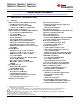
OCTOBER 1994 PGF (S-PQFP-G176) PLASTIC QUAD FLATPACK 132 89 88 133 0,27 0,17 0,08 M 0,50 0,13 NOM 176 45 1 44 Gage Plane 21,50 SQ 24,20 SQ 23,80 26,20 SQ 25,80 0,25 0,05 MIN 0°−ā 7° 0,75 0,45 1,45 1,35 Seating Plane 0,08 1,60 MAX 4040134 / B 03/95 NOTES: A. All linear dimensions are in millimeters. B. This drawing is subject to change without notice. C.
IMPORTANT NOTICE Texas Instruments Incorporated and its subsidiaries (TI) reserve the right to make corrections, enhancements, improvements and other changes to its semiconductor products and services per JESD46, latest issue, and to discontinue any product or service per JESD48, latest issue. Buyers should obtain the latest relevant information before placing orders and should verify that such information is current and complete.