
Serial RapidIO (SRIO) User's Guide


www.ti.com
5.26 DOORBELL n Interrupt Condition Routing Registers (DOORBELL n_ICRR and
SRIO Registers
DOORBELL n_ICRR2)
When doorbell packets are received by the SRIO peripheral, these ICRRs route doorbell interrupt requests
from the associated doorbell ICSR to user-selected interrupt destinations. Each of the four doorbells can
be mapped to these registers (see Table 77 ). The general field description in Table 78 applies to an ICRx
field of either register. For additional programming information, see Section 4.4.1 and Section 2.3.6 .
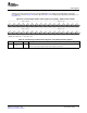
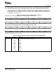
Table 77. DOORBELL n_ICRR Registers
Register Address Offset
DOORBELL0_ICRR 0280h
DOORBELL0_ICRR2 0284h
DOORBELL1_ICRR 0290h
DOORBELL1_ICRR2 0294h
DOORBELL2_ICRR 02A0h
DOORBELL2_ICRR2 02A4h
DOORBELL3_ICRR 02B0h
DOORBELL3_ICRR3 02B4h
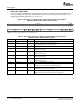
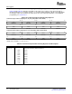
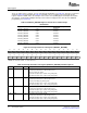
Figure 87. Doorbell n Interrupt Condition Routing Registers
Doorbell n Interrupt Condition Routing Register (DOORBELLn_ICRR)
31 28 27 24 23 20 19 16
ICR7 ICR6 ICR5 ICR4
R/W-0h R/W-0h R/W-0h R/W-0h
15 12 11 8 7 4 3 0
ICR3 ICR2 ICR1 ICR0
R/W-0000 R/W-0000 R/W-0000 R/W-0000
Doorbell n Interrupt Condition Routing Register 2 (DOORBELLn_ICRR2)
31 28 27 24 23 20 19 16
ICR15 ICR14 ICR13 ICR12
R/W-0000 R/W-0000 R/W-0000 R/W-0000
15 12 11 8 7 4 3 0
ICR11 ICR10 ICR9 ICR8
R/W-0000 R/W-0000 R/W-0000 R/W-0000
LEGEND: R/W = Read/Write; - n = Value after reset
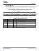
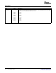
Table 78. DOORBELL n Interrupt Condition Routing Register Field Descriptions
Field Value Description
ICRx Interrupt condition routing. Routes the interrupt request from doorbell n, bit x to one of eight
(x = 0 to 15) interrupt destinations (INTDST0–INTDST7). For example, if ICS6 = 1 in DOORBELL2_ICSR and
ICR6 = 0010b in DOORBELL2_ICRR, the interrupt request from doorbell 2, bit 6 is sent to interrupt
destination 2.
0000b INTDST0
0001b INTDST1
0010b INTDST2
0011b INTDST3
0100b INTDST4
0101b INTDST5
0110b INTDST6
0111b INTDST7
1xxxb Reserved
Serial RapidIO (SRIO)144 SPRUE13A – September 2006
Submit Documentation Feedback