
Serial RapidIO (SRIO) User's Guide

www.ti.com
5.32 INTDST n Interrupt Rate Control Register (INTDST n_RATE_CNTL)
SRIO Registers
There are eight interrupt rate control registers, one for each interrupt destination (see Table 85 ). Figure 93
and Table 86 provide a general description for an interrupt rate control register. These registers are used
to set the rate at which an interrupt can be generated for each interrupt destination. A write to one of the
registers reloads a counter and immediately starts the counter decrementing. When the counter value
reaches 0 (after counting down or after a CPU write of 0), the interrupt logic generates a single interrupt
pulse if any bits in the corresponding ICSR are set (or become set after the zero count is reached). For
additional programming see Section 4.7 .
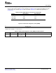
Table 85. INTDST n_RATE_CNTL Registers and the Associated Interrupt
Destinations
Register Address Offset Associated Interrupt
Destination
INTDST0_RATE_CNTL 0320h INTDST0
INTDST1_RATE_CNTL 0324h INTDST1
INTDST2_RATE_CNTL 0328h INTDST2
INTDST3_RATE_CNTL 032Ch INTDST3
INTDST4_RATE_CNTL 0330h INTDST4
INTDST5_RATE_CNTL 0334h INTDST5
INTDST6_RATE_CNTL 0338h INTDST6
INTDST7_RATE_CNTL 033Ch INTDST7
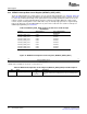
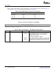
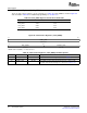
Figure 93. INTDST n Interrupt Rate Control Register (INTDST n_RATE_CNTL)
31 0
COUNT_DOWN_VALUE
R/W-00000000h
LEGEND: R/W = Read/Write; R = Read only; - n = Value after reset
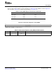
Table 86. INTDST n Interrupt Rate Control Register (INTDST n_RATE_CNTL) Field Descriptions
Bit Field Value Description
31–0 COUNT_DOWN_VALUE 00000000h The value written to this field is immediately transferred to the interrupt
to rate counter, which starts counting down (or causes an interrupt if 0 is
FFFFFFFFh written).
Serial RapidIO (SRIO)154 SPRUE13A – September 2006
Submit Documentation Feedback