
Serial RapidIO (SRIO) User's Guide

www.ti.com
SRIO Functional Description
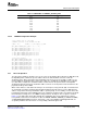
Table 9. SERDES Receive Channel Configuration Register n (SERDES_CFGRX n_CNTL) Field
Descriptions (continued)
Bit Field Value Description
25–24 Reserved 00b Always write 0s to these reserved bits.
23 Reserved 0 This read-only bit returns 0 when read.
22–19 EQ 0000b–1111b Equalizer. Enables and configures the adaptive equalizer to compensate for loss
in the transmission media. For the selectable values, see Table 10 .
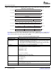
18–16 CDR Clock/data recovery. Configures the clock/data recovery algorithm.
000b First order. Phase offset tracking up to ± 488 ppm.
001b Second order. Highest precision frequency offset matching but poorest response
to changes in frequency offset, and longest lock time. Suitable for use in systems
with fixed frequency offset.
010b Second order. Medium precision frequency offset matching, frequency offset
change response, and lock time.
011b Second order. Best response to changes in frequency offset and fastest lock time,
but lowest precision frequency offset matching. Suitable for use in systems with
spread spectrum clocking.
100b First order with fast lock. Phase offset tracking up to ± 1953 ppm in the presence of
..10101010.. training pattern, and ± 448 ppm otherwise.
101b Second order with fast lock. As per setting 001, but with improved response to
changes in frequency offset when not close to lock.
110b Second order with fast lock. As per setting 010, but with improved response to
changes in frequency offset when not close to lock.
111b Second order with fast lock. As per setting 011, but with improved response to
changes in frequency offset when not close to lock.
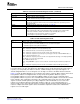
15–14 LOS Loss of signal. Enables loss of signal detection with 2 selectable thresholds.
00b Disabled. Loss of signal detection disabled.
01b High threshold. Loss of signal detection threshold in the range 85 to 195mV
dfpp
.
This setting is suitable for Infiniband.
10b Low threshold. Loss of signal detection threshold in the range 65 to 175mV
dfpp
.
This setting is suitable for PCI-E and S-ATA.
11b Reserved
13–12 ALIGN Symbol alignment. Enables internal or external symbol alignment.
00b Alignment disabled. No symbol alignment will be performed while this setting is
selected, or when switching to this selection from another.
01b Comma alignment enabled. Symbol alignment will be performed whenever a
misaligned comma symbol is received.
10b Alignment jog. The symbol alignment will be adjusted by one bit position when this
mode is selected (that is, the ALIGN value changes from 0xb to 1xb).
11b Reserved
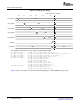
11 Reserved 0 This read-only bit returns 0 when read.
10–8 TERM 001b Input termination. The only valid value for this field is 001b; all other values are
reserved. The value 001b sets the common point to 0.8 VDDT and supports AC
coupled systems using CML transmitters. The transmitter has no effect on the
receiver common mode, which is set to optimize the input sensitivity of the
receiver. Common mode termination is via a 50 pF capacitor to VSSA.
7 INVPAIR Invert polarity. Inverts polarity of RIORXn and RIORXn.
0 Normal polarity. RIORXn is considered to be positive data and RIORXn negative.
1 Inverted polarity. RIORXn is considered to be negative data and RIORXn positive.
6–5 RATE Operating rate. Selects full, half, or quarter rate operation.
00b Full rate. Two data samples taken per PLL output clock cycle.
01b Half rate. One data sample taken per PLL output clock cycle.
10b Quarter rate. One data sample taken every two PLL output clock cycles.
11b Reserved
32 Serial RapidIO (SRIO) SPRUE13A – September 2006
Submit Documentation Feedback