
Serial RapidIO (SRIO) User's Guide

www.ti.com
SRIO Functional Description
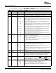
Table 14. LSU Control/Command Register Fields (continued)
LSU Register Field RapidIO Packet Header Field
DestID RapidIO destinationID field specifying the target device.
Packet Type 4 MSBs: 4-bit ftype field for all packets
4 LSBs: 4-bit trans field for packet types 2, 5, and 8
OutPortID Not available in RapidIO header.
Indicates the output port number for the packet to be transmitted from. Specified by the CPU
along with NodeID.
Drbll Info RapidIO doorbell info field for type 10 packets. (see Table 23 )
Hop Count RapidIO hop_count field specified for Type 8 Maintenance packets.
Interrupt Req Not available in RapidIO header.
CPU controlled request bit used for interrupt generation. Typically used in conjunction with
non-posted commands to alert the CPU when the requested data/status is present.
0 - An interrupt is not requested upon completion of command
1- An interrupt is requested upon completion of command
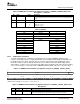
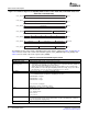
Table 15. LSU Status Register Fields
LSU Register Field Function
BSY Indicates status of the command registers.
0 - Command registers are available (writable) for next set of transfer descriptors
1 - Command registers are busy with current transfer
Completion Code Indicates the status of the pending command.
000b – Transaction complete, no errors (Posted/Non-posted)
001b – Transaction timeout occurred on Non-posted transaction
010b – Transaction complete, packet not sent due to flow control blockade (Xoff)
011b – Transaction complete, non-posted response packet (type 8 and 13) contained ERROR status, or
response payload length was in error
100b – Transaction complete, packet not sent due to unsupported transaction type or invalid programming
encoding for one or more LSU register fields
101b – DMA data transfer error
110b – Retry DOORBELL response received, or Atomic Test-and-swap was not allowed (semaphore in
use)
111b – Transaction complete, packet not sent due to unavailable outbound credit at given priority
(1)
(1)
Status available only when busy (BSY) signal = 0.
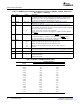
Four LSU register sets exist. This allows four outstanding requests for all transaction types that require a
response (i.e., non-posted). For multi-core devices, software manages the usage of the registers. A
shared configuration bus accesses all register sets. A single core device can utilize all four LSU blocks.
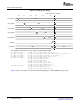
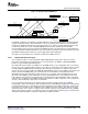
Figure 13 shows the timing diagram for accessing the LSU registers. The busy (BSY) signal is deasserted.
LSU n_REG1 is written on configuration bus clock cycle T0, LSU n_REG2 is written on cycle T1,
LSU n_REG3 is written on cycle T2, and LSU n_REG4 is written on cycle T3. The command register
LSU n_REG5 is written on cycle T4. The extended address field in LSU n_REG0 is assumed to be constant
in this example. Upon completion of the write to the command register (next clock cycle T5), the BSY
signal is asserted, at which point the preceding completion code is invalid and accesses to the LSU
registers are not allowed. Once the transaction completes (either as a successful transmission, or
unsuccessfully, such as flow control prevention or response timeout) and any required interrupt service
routine is completed, the BSY signal is deasserted and the completion code becomes valid and the
registers are accessible again.
SPRUE13A – September 2006 Serial RapidIO (SRIO) 37
Submit Documentation Feedback