
Serial RapidIO (SRIO) User's Guide


www.ti.com
Reserved
RIO_LSUn_FLOW_MASKS
(AddressOffsets:0x041C,
0x043C,0x045C,0x047C)
31-16
R,0x0000
LSUnFlowMask
15-0
R/W,0xFFFF
TXQueue1
FlowMask
RIO_TX_CPPI_FLOW_MASKS0
(AddressOffsets:0x0704)
31-16
R/W,0xFFFF
TXQueue0
FlowMask
15-0
R/W,0xFFFF
TXQueue3
FlowMask
RIO_TX_CPPI_FLOW_MASKS1
(AddressOffsets:0x0708)
31-16
R/W,0xFFFF
TXQueue2
FlowMask
15-0
R/W,0xFFFF
TXQueue5
FlowMask
RIO_TX_CPPI_FLOW_MASKS2
(AddressOffsets:0x070C)
31-16
R/W,0xFFFF
TXQueue4
FlowMask
15-0
R/W,0xFFFF
TXQueue7
FlowMask
RIO_TX_CPPI_FLOW_MASKS3
(AddressOffsets:0x0710)
31-16
R/W,0xFFFF
TXQueue6
FlowMask
15-0
R/W,0xFFFF
TXQueue9
FlowMask
RIO_TX_CPPI_FLOW_MASKS4
(AddressOffsets:0x0714)
31-16
R/W,0xFFFF
TXQueue8
FlowMask
15-0
R/W,0xFFFF
TXQueue11
FlowMask
RIO_TX_CPPI_FLOW_MASKS5
(AddressOffsets:0x0718)
31-16
R/W,0xFFFF
TXQueue10
FlowMask
15-0
R/W,0xFFFF
TXQueue13
FlowMask
RIO_TX_CPPI_FLOW_MASKS6
(AddressOffsets:0x071C)
31-16
R/W,0xFFFF
TXQueue12
FlowMask
15-0
R/W,0xFFFF
TXQueue15
FlowMask
RIO_TX_CPPI_FLOW_MASKS7
(AddressOffsets:0x0720)
31-16
R/W,0xFFFF
TXQueue14
FlowMask
15-0
R/W,0xFFFF
SRIO Functional Description
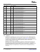
Table 24. Flow Control Table Entry Register n (FLOW_CNTL n) Field Descriptions
Bit Field Value Description
31–18 Reserved 0 These read-only bits return 0s when read.
17–16 TT Transfer type for flow n
00b 8-bit destination IDs
01b 16-bit destination IDs
1xb Reserved
15–0 FLOW_CNTL_ID 0000h–FFFFh Destination ID for flow n. When 8-bit destination IDs are used (TT = 00b),
the 8 MSBs of this field are don't care bits.
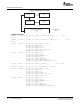
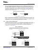
Each transmit source, including any LSU and any TX CPPI queue, indicates which of the 16 flows it uses
with a 16-bit flow mask. Figure 28 illustrates the registers that contain the flow masks, and Figure 29
illustrates the general form of an individual flow mask. As can be seen from Table 25 , bits 0 through 15 of
the flow mask correspond to flows 0 through 15, respectively.
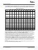
The CPU must configure the flow masks upon reset. The default setting is all 1s, indicating that the
transmit source supports all flows. If the register is set to all 0s, the transmit source does not support any
flow, and consequently, that source is never flow-controlled. If any of the table entry counters that a
transmit source supports have a corresponding non-zero Xoff count, the transmit source is flow-controlled.
A simple 16-bit bus indicates the Xoff state of all 16 flows and is compared to the transmit source mask
register. Each source interprets this result and performs flow control accordingly. For example, an LSU
module that is flow-controlled can reload its registers and attempt to send a packet to another flow, while a
TX CPPI queue that is flow-controlled may create HOL blocking issues on that queue.
Figure 28. Transmit Source Flow Control Masks
LEGEND: R/W = Read/Write; R = Read only; - n = Value after reset
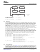
Figure 29. Fields Within Each Flow Mask
15 14 13 12 11 10 9 8 7 6 5 4 3 2 1 0
FL15 FL14 FL13 FL12 FL11 FL10 FL9 FL8 FL7 FL6 FL5 FL4 FL3 FL2 FL1 FL0
R/W-1 R/W-1 R/W-1 R/W-1 R/W-1 R/W-1 R/W-1 R/W-1 R/W-1 R/W-1 R/W-1 R/W-1 R/W-1 R/W-1 R/W-1 R/W-1
LEGEND: R/W = Read/Write; - n = Value after reset
SPRUE13A – September 2006 Serial RapidIO (SRIO) 67
Submit Documentation Feedback