
Serial RapidIO (SRIO) User's Guide

www.ti.com
2.3.15.2 Daisy Chain Operation and Packet Forwarding
2.3.15.3 Enabling Multicast and Packet Forwarding
SRIO Functional Description
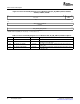
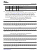
Table 31. Multicast DeviceID Operation
Local DeviceID Multicast DeviceID
Device Register Offset Register Offset Endpoint Device Requirements
TMS320TCI6482 0080h 0084h Accepts discrete multiple DestIDs from
incoming packet
Some applications may require daisy chaining of devices together versus using a switch fabric. Typically,
these applications are low cost implementations. Daisy chains have variable system latency depending on
device position within the chain. Daisy chain implementations also have reduced bandwidth capabilities,
since the link bandwidth doesn’t change, the bandwidth allocated to each device in the chain is limited
(sum of devices’ individual bandwidth needs can’t exceed link bandwidth).
To support daisy chain or ring topologies, the peripheral features a hardware packet forwarding function.
This feature eliminates the need for software to be involved in routing a packet to the next device in the
chain. The basic idea behind the hardware packet forwarding logic is to provide an input port to output
port path such that the packets never leave the peripheral (no DMA transfer). A simple check of an
in-coming packet’s DestID versus the device’s DeviceID and MulticastID is done to determine if the packet
should be forwarded. If the packet’s DestID matches DeviceID, the packet is accepted and processed by
the device. If the packet’s DestID matches the MulticastID, the packet is accepted by the device and
forwarded based on the rules outlined in Section 2.3.15.1 . If the packet’s DestID doesn’t match either, the
packet is simply destroyed or forwarded, depending on the whether the hardware packet forwarding is
enabled.
Additionally, it is beneficial to be able to only forward a packet if the destination ID is one of the devices in
the chain/ring. Otherwise, a rogue packet may be forwarded endlessly using up valuable bandwidth. The
hardware packet forwarding uses a 4 entry mapping table shown in Table 32 and Table 33 . These
mapping entries allow programmable selection of output port based on the in-coming packets DestID
range. Since the packet forwarding is done at the logical layer and not the physical layer, CRCs will be
regenerated for each forwarded packet.
In order to enable multicast support, bit 5 of the SP_IP_MODE (offset 0x12004) must be set to 1.The
multicast mode is disabled by simply writing the same deviceID into the registers listed in Table 31 .
Hardware packet forwarding can be disabled by assigning all the table entry Upper and Lower deviceID
boundaries equal to the local DeviceID value.
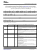
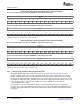
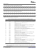
Figure 42. Packet Forwarding Register n for 16-Bit Device IDs (PF_16B_CNTL n) Offsets 0x0090,
0x0098, 0x00A0, 0x00A8
31 16 15 0
16BIT_DEVID_UP_BOUND 16BIT_DEVID_LOW_BOUND
R/W-FFFFh R/W-FFFFh
LEGEND: R/W = Read/Write; - n = Value after reset
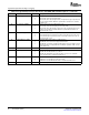
Table 32. Packet Forwarding Register n for 16-Bit DeviceIDs (PF_16B_CNTL n) Field Descriptions
Bit Field Value Description
31–16 16BIT_DEVID_UP_BOUND 0000h–FFFFh Upper 16-bit DeviceID boundary. DestID above this range
cannot use the table entry.
15–0 16BIT_DEVID_LOW_BOUND 0000h–FFFFh Lower 16-bit DeviceID boundary. DestID lower than this
number cannot use the table entry.
SPRUE13A – September 2006 Serial RapidIO (SRIO) 81
Submit Documentation Feedback