
Serial RapidIO (SRIO) User's Guide

www.ti.com
4.3.2 CPPI Interrupt Condition Status and Clear Registers
Interrupt Conditions
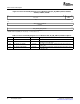
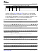
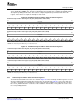
Figure 48. Doorbell 2 Interrupt Condition Status and Clear Registers
Doorbell 2 Interrupt Condition Status Register (DOORBELL2_ICSR) (Address Offset 0220h)
31 16
Reserved
R-0
15 14 13 12 11 10 9 8 7 6 5 4 3 2 1 0
ICS15 ICS14 ICS13 ICS12 ICS11 ICS10 ICS9 ICS8 ICS7 ICS6 ICS5 ICS4 ICS3 ICS2 ICS1 ICS0
R-0 R-0 R-0 R-0 R-0 R-0 R-0 R-0 R-0 R-0 R-0 R-0 R-0 R-0 R-0 R-0
Doorbell 2 Interrupt Condition Clear Register (DOORBELL2_ICCR) (Address Offset 0228h)
31 16
Reserved
R-0
15 14 13 12 11 10 9 8 7 6 5 4 3 2 1 0
ICC15 ICC14 ICC13 ICC12 ICC11 ICC10 ICC9 ICC8 ICC7 ICC6 ICC5 ICC4 ICC3 ICC2 ICC1 ICC0
W-0 W-0 W-0 W-0 W-0 W-0 W-0 W-0 W-0 W-0 W-0 W-0 W-0 W-0 W-0 W-0
LEGEND: R = Read only; W = Write only; - n = Value after reset
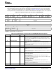
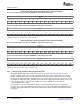
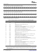
Figure 49. Doorbell 3 Interrupt Condition Status and Clear Registers
Doorbell 3 Interrupt Condition Status Register (DOORBELL3_ICSR) (Address Offset 0230h)
31 16
Reserved
R-0
15 14 13 12 11 10 9 8 7 6 5 4 3 2 1 0
ICS15 ICS14 ICS13 ICS12 ICS11 ICS10 ICS9 ICS8 ICS7 ICS6 ICS5 ICS4 ICS3 ICS2 ICS1 ICS0
R-0 R-0 R-0 R-0 R-0 R-0 R-0 R-0 R-0 R-0 R-0 R-0 R-0 R-0 R-0 R-0
Doorbell 3 Interrupt Condition Clear Register (DOORBELL3_ICCR) (Address Offset 0238h)
31 16
Reserved
R-0
15 14 13 12 11 10 9 8 7 6 5 4 3 2 1 0
ICC15 ICC14 ICC13 ICC12 ICC11 ICC10 ICC9 ICC8 ICC7 ICC6 ICC5 ICC4 ICC3 ICC2 ICC1 ICC0
W-0 W-0 W-0 W-0 W-0 W-0 W-0 W-0 W-0 W-0 W-0 W-0 W-0 W-0 W-0 W-0
LEGEND: R = Read only; W = Write only; - n = Value after reset
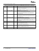
The ICSRs and the ICCRs for the RXU and the TXU are shown in Figure 50 and Figure 51 . These
interrupt condition registers are used when the SRIO peripheral receives and transmits data message
packets. Each ICS bit corresponds to the interrupt for one of the buffer descriptor queues. For example,
the bits ICS15, ICS8, and ICS0 of RX_CPPI_ICSR correspond to RX buffer descriptor queues 15, 8, and
0. Similarly, the bits ICS15, ICS8, and ICS0 of TX_CPPI_ICSR support TX buffer descriptor queues 15, 8,
and 0. The 16 ICC bits of each interrupt condition clear register (ICCR) are used to clear the
corresponding bits in the ICSR.
For reception, the clearing of any ICSR bit depends on the CPU writing the value of the last buffer
descriptor processed to the completion pointer (CP) register for the queue (QUEUE n_RXDMA_CP). Port
hardware clears the ICSR bit only if the CP value written by the CPU equals the port written value in the
CP register.
88 Serial RapidIO (SRIO) SPRUE13A – September 2006
Submit Documentation Feedback