
Stereo System - Digital Audio Signal Processor User Manual

SPRS079E – OCTOBER 1998 – REVISED AUGUST 2000
61
POST OFFICE BOX 1443 • HOUSTON, TEXAS 77251–1443
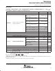
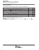
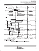
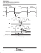
HPI8 timing
switching characteristics over recommended operating conditions
†‡§¶
[H = 0.5t
c(CO)
]
(see Figure 35, Figure 36, Figure 37, and Figure 38)
PARAMETER MIN MAX UNIT
t
en(DSL-HD)
Enable time, HD driven from DS low 2 16 ns
Case 1a: Memory accesses when
DMAC is active in 16-bit mode and
t
w(DSH)
< 18H
18H+16 – t
w(DSH)
Case 1b: Memory accesses when
DMAC is active in 16-bit mode and
t
w(DSH)
≥ 18H
16
t
d(DSL HDV1)
Delay time, DS low to HDx valid for
Case 1c: Memory access when
DMAC is active in 32-bit mode and
t
w(DSH)
< 26H
26H+16 – t
w(DSH)
ns
t
d(DSL-HDV1)
Delay
time
,
DS
low
to
HDx
valid
for
first byte of an HPI read
Case 1d: Memory access when
DMAC is active in 32-bit mode and
t
w(DSH)
≥ 26H
16
ns
Case 2a: Memory accesses when
DMAC is inactive and t
w(DSH)
< 10H
10H+16 – t
w(DSH)
Case 2b: Memory accesses when
DMAC is inactive and t
w(DSH)
≥ 10H
16
Case 3: Register accesses 16
t
d(DSL-HDV2)
Delay time, DS low to HDx valid for second byte of an HPI read 16 ns
t
h(DSH-HDV)R
Hold time, HDx valid after DS high, for a HPI read 3 5 ns
t
v(HYH-HDV)
Valid time, HDx valid after HRDY high 9
t
d(DSH-HYL)
Delay time, DS high to HRDY low (see Note 1) 16 ns
Case 1a: Memory accesses when
DMAC is active in 16-bit mode
18H+16 ns
t
Delay time DS high to HRDY high
Case 1b: Memory accesses when
DMAC is active in 32-bit mode
26H+16
ns
t
d(DSH-HYH)
Delay time, DS high to HRDY high
Case 2: Memory accesses when
DMAC is inactive
10H+16
ns
Case 3: Write accesses to HPIC
register (see Note 2)
6H+16
ns
t
d(HCS-HRDY)
Delay time, HCS low/high to HRDY low/high
16 ns
t
d(COH-HYH
) Delay time, CLKOUT high to HRDY high 3 ns
t
d(COH-HTX)
Delay time, CLKOUT high to HINT change 5 ns
t
d(COH-GPIO)
Delay time, CLKOUT high to HDx output change. HDx is configured as a
general-purpose output.
6 ns
NOTES: 1. The HRDY output is always high when the HCS input is high, regardless of DS timings.
2. This timing applies when writing a one to the DSPINT bit or HINT bit of the HPIC register. All other writes to the HPIC occur
asynchronoulsy, and do not cause HRDY to be deasserted.
†
DS refers to the logical OR of HCS
, HDS1, and HDS2.
‡
HDx refers to any of the HPI data bus pins (HD0, HD1, HD2, etc.).
§
DMAC stands for direct memory access (DMA) controller. The HPI8 shares the internal DMA bus with the DMAC, thus HPI8 access times are
affected by DMAC activity.
¶
GPIO refers to the HD pins when they are configured as general-purpose input/outputs.