
Car Stereo System User Manual

www.ti.com
Power Management
1.5.3.2.1 Peripheral Clock Gating Configuration Registers (PCGCR1 and PCGCR2) [1C02 - 1C03h]
The peripheral clock gating configuration registers (PCGRC1 and PCGCR2) are used to disable the clocks
of the DSP peripherals. In contrast to the idle control register (ICR), these bits take effect within 6
SYSCLK cycles and do not require an idle instruction.
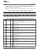
The peripheral clock gating configuration register 1 (PCGCR1) is shown in Figure 1-14 and described in
Table 1-24.
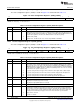
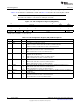
Figure 1-14. Peripheral Clock Gating Configuration Register 1 (PCGCR1) [1C02h]
15 14 13 12 11 10 9 8
SYSCLKDIS I2S2CG TMR2CG TMR1CG EMIFCG TMR0CG I2S1CG I2S0CG
R/W-0 R/W-0 R/W-0 R/W-0 R/W-0 R/W-0 R/W-0 R/W-0
7 6 5 4 3 2 1 0
MMCSD1CG I2CCG Reserved MMCSD0CG DMA0CG UARTCG SPICG I2S3CG
R/W-0 R/W-0 R/W-0 R/W-0 R/W-0 R/W-0 R/W-0 R/W-0
LEGEND: R/W = Read/Write; R = Read only; -n = value after reset
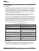
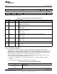
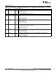
Table 1-24. Peripheral Clock Gating Configuration Register 1 (PCGCR1) Field Descriptions
Bit Field Value Description
15 SYSCLKDIS System clock disable bit. This bit can be used to turn off the system clock. Setting the WAKEUP pin
high enables the system clock. Since the WAKEUP pin is used to re-enable the system clock, the
WAKEUP pin must be low to disable the system clock.
NOTE Disabling the system clock disables the clock to most parts of the DSP, including the CPU.
0 System clock is active.
1 System clock is disabled.
14 I2S2CG I2S2 clock gate control bit. This bit is used to enable and disable the I2S2 peripheral clock.
0 Peripheral clock is active.
1 Peripheral clock is disabled.
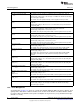
13 TMR2CG Timer 2 clock gate control bit. This bit is used to enable and disable the Timer 2 peripheral clock.
0 Peripheral clock is active.
1 Peripheral clock is disabled.
12 TMR1CG Timer 1 clock gate control bit. This bit is used to enable and disable the Timer 1 peripheral clock.
0 Peripheral clock is active.
1 Peripheral clock is disabled.
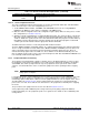
11 EMIFCG EMIF clock gate control bit. This bit is used to enable and disable the EMIF peripheral clock. NOTE
You must request permission before stopping the EMIF clock through the peripheral clock stop
request/acknowledge register (CLKSTOP).
0 Peripheral clock is active.
1 Peripheral clock is disabled.
10 TMR0CG Timer 0 clock gate control bit. This bit is used to enable and disable the Timer 0 peripheral clock.
0 Peripheral clock is active.
1 Peripheral clock is disabled.
9 I2S1CG I2S1 clock gate control bit. This bit is used to enable and disable the I2S1 peripheral clock.
0 Peripheral clock is active.
1 Peripheral clock is disabled.
8 I2S0CG I2S0 clock gate control bit. This bit is used to enable and disable the I2S0 peripheral clock.
0 Peripheral clock is active.
1 Peripheral clock is disabled.
7 MMCSD1CG MMC/SD1 clock gate control bit. This bit is used to enable and disable the MMC/SD1 peripheral
clock.
0 Peripheral clock is active.
1 Peripheral clock is disabled.
39
SPRUFX5A–October 2010–Revised November 2010 System Control
Submit Documentation Feedback
Copyright © 2010, Texas Instruments Incorporated