
Network Router User Manual
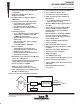


TMS380C26
NETWORK COMMPROCESSOR
SPWS010A–APRIL 1992–REVISED MARCH 1993
POST OFFICE BOX 1443 • HOUSTON, TEXAS
77251–1443
4
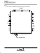
block diagram and signal descriptions
TMS380C26 has a bus interface to the host system, a bus interface to local memory, and an interface to the
physical layer circuitry. As a rule of thumb in the pin nomenclature and descriptions that follow, pin names
starting with the letter S attach to the host system bus and pin names starting with the letter M attach to the local
memory bus. Active-low signals have names with overbars, e.g., SCS
.
Protocol Handler (PH):
for Token Ring and
Ethernet Interface
SADH0
SADH7
SADL0
SADL7
SPH
SPL
SBRLS
SINTR/SIRQ
SDDIR
SDBEN
SALE
SXAL
SOWN
SIACK
SBCLK
SRD
/SUDS
SWR/SLDS
SRDY/SDTACK
SI/M
SHLDA/SBGR
SBHE/SRNW
SRAS/SAS
S8/SHALT
SRESET
SRS0
SRS1
SRS2/SBERR
SCS
SRSX
SHRQ/SBRQ
NSELOUT0
RCLK/RXC
REDY
/CRS
WFLT
/COLL
RCVR/RXD
PXTALIN/TXC
MADH0
MADH7
MADL0
MADL7
MRAS
MCAS
MAXPH
MAXPL
MW
MOE
MDDIR
MAL
MAX0
MAX2
MRESET
MROMEN
MBEN
MBRQ
MBGR
MACS
MBIAEN
MREF
OSCIN
OSCOUT
MBCLK1
SYNCIN
CLKDIV
NMI
EXTINT0
EXTINT
3
TEST0
TEST5
XMATCH
XFAIL
FRAQ/TXD
NSRT
/LPBK
WRAP
/TXEN
DRVR
DRVR
MBCLK2
System
Interface
(SIF)
Memory
Interface
(MIF)
• DRAM Refresh
• Local Bus
Arbitrator
• Local Bus
Control
• Local
Parity Check/
Generator
• DIO Control
• Bus Control
• DMA Control
Clock
Generator
(CG)
Adapter
Support
Function
(ASF)
Communications
Processor
• Interrupts
• Test Function
SBBSY
BTSTRP
PRTYEN
NSELOUT1
Figure 2. TMS380C26 COMMprocessor Block Diagram