
Network Router User Manual
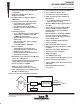


TMS380C26
NETWORK COMMPROCESSOR
SPWS010A–APRIL 1992–REVISED MARCH 1993
POST OFFICE BOX 1443 • HOUSTON, TEXAS
77251–1443
5
Terminal Functions
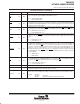
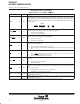
PIN NAME NO. I/O DESCRIPTION
BTSTRP 23 IN
Bootstrap. The value on this pin is loaded into the BOOT bit of the SIFACL register at reset (i.e., when
the SRESET
pin is asserted or the ARESET bit in the SIFACL register is set) to form a default value.
This bit indicates whether chapters 0 and 31 of the memory map are RAM or ROM. If these chapters
are RAM then the TMS380C26 is denied access to the local memory bus until the CPHALT bit in the
SIFACL register is cleared.
H = Chapters 0 and 31 of local memory are RAM-based (see Note 1).
L = Chapters 0 and 31 of local memory are ROM-based.
CLKDIV 19 IN
Clock Divider Select. This pin must be pulled high
H = Indicates 64-MHz OSCIN (see Note 3).
L = Reserved.
EXTINT0
EXTINT1
EXTINT2
EXTINT3
14
13
12
11
IN Reserved; must be pulled high (see Note 4).
MACS 104 IN Reserved. Must be tied low (see Note 2).
MADH0
MADH1
MADH2
MADH3
MADH4
MADH5
MADH6
MADH7
129
128
127
126
123
122
121
120
I/O
Local memory Address, Data and Status Bus – high byte. For the first quarter of the local memory
cycle these bus lines carry address bits AX4 and A0 to A6; for the second quarter, they carry status
bits; and for the third and fourth quarters, they carry data bits 0 to 7. The most significant bit is MADH0
and the least significant bit is MADH7.
Memory Cycle
1Q
2Q 3Q 4Q
Signal AX4,A0–A6 Status D0–D7 D0–D7
MADL0
MADL1
MADL2
MADL3
MADL4
MADL5
MADL6
MADL7
10
9
8
7
6
5
4
3
I/O
Local Memory Address, Data and Status Bus – low byte. For the first quarter of the local memory
cycle, these bus lines carry address bits A7 to A14; for the second quarter, they carry address bits
AX4 and A0 to A6; and for the third and fourth quarters, they carry data bits 8 to 15. The most
significant bit is MADL0 and the least significant bit is MADL7.
Memory Cycle
1Q
2Q 3Q 4Q
Signal A7–A14 AX4,A0–A6 D8–D15 D8–D15
MAL 103 OUT
Memory Address Latch. This is a strobe signal for sampling the address at the start of the memory
cycle; it is used by SRAMs and EPROMs. The full 20-bit word address is valid on MAX0, MAXPH,
MAX2, MAXPL, MADH0-MADH7, and MADL0-MADL7. Three 8-bit transparent latches can therefore
be used to retain a 20-bit static address throughout the cycle.
Rising edge = No signal latching.
Falling edge = Allows the above address signals to be latched.
MAX0 111 OUT
Memory Cycle
1Q
2Q 3Q 4Q
Signal AX0 A12 A12 A12
Local Memory Extended Address Bit. This signal drives AX0 at ROW address time and it drives A12
at COL address and DATA time for all cycles. This signal can be latched by MRAS
. Driving A12 eases
interfacing to a BIA ROM.
MAX2 112 OUT
Memory Cycle
1Q
2Q 3Q 4Q
Signal AX2 A14 A14 A14
Local Memory Extended Address Bit. This signal drives AX2 at ROW address time, which can be
latched by MRAS
, and A14 at COL address, and DATA time for all cycles. Driving A14 eases
interfacing to a BIA ROM.
NOTES: 1. Pin has an internal pullup device to maintain a high voltage level when left unconnected (no etch or loads).
2. Pin should be connected to ground.
3. Pin should be tied to V
CC
with a 4.7-kΩ pullup resistor.
4. Each pin must be individually tied to V
CC
with a 1.0-kΩ pullup resistor.