
Network Router User Manual
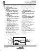


TMS380C26
NETWORK COMMPROCESSOR
SPWS010A–APRIL 1992–REVISED MARCH 1993
POST OFFICE BOX 1443 • HOUSTON, TEXAS
77251–1443
6
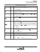
Terminal Functions (continued)
PIN NAME NO. I/O DESCRIPTION
MAXPH 130 I/O
Local Memory Extended Address and Parity High Byte. For the first quarter of a memory cycle this
signal carries the extended address bit (AX1); for the second quarter of a memory cycle this signal
carries the extended address bit (AX0); and for the last half of the memory cyle this signal carries the
parity bit for the high data byte.
Memory Cycle
1Q
2Q 3Q 4Q
Signal AX1 AX0 Parity Parity
MAXPL 2 I/O
Local Memory Extended Address and Parity Low Byte. For the first quarter of a memory cycle this
signal carries the extended address bit (AX3), for the second quarter of a memory cycle this signal
carries extended address bit (AX2); and for the last half of the memory cycle this signal carries the
parity bit for the low data byte.
Memory Cycle
1Q
2Q 3Q 4Q
Signal AX3 AX2 Parity Parity
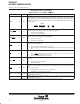
MBCLK1
MBCLK2
97
98
OUT
Local Bus Clock1 and local Bus Clock 2. These signals are referenced for all local bus transfers.
MBCLK2 lags MBCLK1 by a quarter of a cycle. These clocks operate at 8 MHz for a 64-MHz OSCIN
and 6 MHz for a 48-MHz OSCIN, which is twice the memory cycle rate. The MBCLK signals are
always a divide-by-8 of the OSCIN frequency.
MBEN 119 OUT
Buffer Enable. This signal enables the bidirectional buffer outputs on the MADH, MAXPH, MAXPL,
and MADL buses during the data phase. This signal is used in conjunction with MDDIR which selects
the buffer output direction.
H = Buffer output disabled.
L = Buffer output enabled.
MBGR 132 OUT Reserved. Must be left unconnected.
MBIAEN 101 OUT
Burned-In Address Enable. This is an output signal used to provide an output enable for the ROM
containing the adapter’s Burned-In Address (BIA).
H = This signal is driven high for any WRITE accesses to the addresses between >00.0000 and
>00.000F, or any accesses (Read/Write) to any other address.
L = This signal is driven low for any READ from addresses between >00.0000 and >00.000F.
MBRQ 131 IN Reserved. Must be pulled high (see Note 4).
MCAS 113 OUT
Column Address Strobe for DRAMs. The column address is valid for the 3/16 of the memory cycle
following the row address portion of the cycle. This signal is driven low every memory cycle while the
column address is valid on MADL0-MADL7, MAXPH, and MAXPL, except when one of the following
conditions occurs:
1) When the address accessed is in the BIA ROM (>00.0000 – >00.000F).
2) When the address accessed is in the EPROM memory map (i.e., when the BOOT bit in
the SIFACL register is zero and an access is made between >00.0010 – >00.FFFF)
or >1F.0000 – >1F.FFFF).
3) When the cycle is a refresh cycle, in which case MCAS
is driven at the start of the cycle before
MRAS
(for DRAMs that have CAS-before-RAS refresh). For DRAMs that do not support CAS-
before-RAS
refresh, it may be necessary to disable MCAS with MREF during the refresh
cycle.
MDDIR 110 OUT
Data Direction. This signal is used as a direction control for bidirectional bus drivers. The signal
becomes valid before MBEN
active.
H = TMS380C26 memory bus write.
L = TMS380C26 memory bus read.
NOTE 4: Each pin must be individually tied to V
CC
with a 1.0-kΩ pullup resistor.