
Network Router User Manual
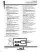
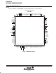


TMS380C26
NETWORK COMMPROCESSOR
SPWS010A–APRIL 1992–REVISED MARCH 1993
POST OFFICE BOX 1443 • HOUSTON, TEXAS
77251–1443
7
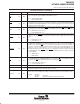
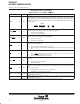
Terminal Functions (continued)
PIN NAME NO. I/O DESCRIPTION
MOE 118 OUT
Memory Output Enable. This signal is used to enable the outputs of the DRAM memory during a read
cycle. This signal is high for EPROM or BIA ROM read cycles.
H = Disable DRAM outputs.
L = Enable DRAM outputs.
MRAS 115 OUT
Row Address Strobe for DRAMs. The row address lasts for the first 5/16 of the memory cycle. This
signal is driven low every memory cycle while the row address is valid on MADL0-MADL7, MAXPH,
and MAXPL for both RAM and ROM cycles. It is also driven low during refresh cycles when the refresh
address is valid on MADL0-MADL7.
MREF 102 OUT
DRAM Refresh Cycle in Progress. This signal is used to indicate that a DRAM refresh cycle is
occurring. It is also used for disabling MCAS
to all DRAMs that do not use a CAS before-RAS refresh.
H = DRAM refresh cycle in process.
L = Not a DRAM refresh cycle.
MRESET 99 OUT
Memory Bus Reset. This is a reset signal generated when either the ARESET bit in the SIFACL
register is set or the SRESET
pin is asserted. This signal is used for resetting external local bus glue
logic.
H = External logic not reset.
L = External logic reset.
MROMEN 105 OUT
ROM Enable. During the first 5/16 of the memory cycle, this signal is used to provide a chip select
for ROMs when the BOOT bit of the SIFACL register is zero (i.e., when code is resident in ROM, not
RAM). It can be latched by MA
L. It goes low for any read from addresses >00.0010 – >00.FFFF or
>1F.0000 – >1F.FFFF when the Boot bit in the SIFACL register is zero. It stays high for writes to these
addresses, accesses of other addresses, or accesses of any address when the BOOT bit is one.
During the final three quarters of the memory cycle, it outputs the A13 address signal for interfacing
to a BIA ROM. This means MBIAEN
, MAX0, ROMEN, and MAX2 together form a glueless interface
for the BIA ROM.
H = ROM disabled.
L = ROM enabled.
MW 114 OUT
Local Memory Write. This signal is used to specify a write cycle on the local memory bus. The data
on the MADH0-MADH7 and MADL0-MADL7 buses is valid while MW
is low. DRAMs latch data on
the falling edge MW
, while SRAMs latch data on the rising edge of MW.
H = Not a local memory write cycle.
L = Local memory write cycle.
NMI 15 IN Non-Maskable Interrupt Request. This pin must be left unconnected.
OSCIN 107 IN
External Oscillator Input. This line provides the clock frequency to the TMS380C26 for a 4-MHz
internal bus. OSCIN should be 64 a MHz signal (see Note 5).
OSCOUT 96 OUT
Oscillator Output. With OSCIN at 64 MHz and CLKDIV pulled high, this pin provides an 8 MHz output
which can be used by TMS3054 for 4 Mbps operation without the need for an additional crystal.
CLKDIV OSCOUT
L Reserved (Reserved)
H OSCIN/8 (if OSCIN = 64 MHz, then OSCOUT = 8 MHz).
NOTE 5: Pin has an expanded input voltage specification.