ThunderLAN TNETE100A, TNETE110A, TNETE211 Programmer’s Guide October 1996 Network Business Products
Printed in U.S.A.
t ThunderLAN Programmer’s Guide TNETE100A, TNETE110A, TNETE211 Literature Number: SPWU013A Manufacturing Part Number: L411001-9761 revision A October 1996
Running Title—Attribute Reference IMPORTANT NOTICE Texas Instruments (TI) reserves the right to make changes to its products or to discontinue any semiconductor product or service without notice, and advises its customers to obtain the latest version of relevant information to verify, before placing orders, that the information being relied on is current.
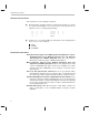
Preface Read This First About This Manual The ThunderLAN Programmer’s Guide assists you in using the following implementations of ThunderLAN networking hardware: - t TNETE100A Ethernet controller TNETE110A Ethernet controller TNETE211 100 VG-AnyLAN physical media interface (PMI) How to Use This Manual The goal of this book is to assist you in the development of drivers for the ThunderLAN controllers.
Notational Conventions Notational Conventions This document uses the following conventions: - Program listings, program examples, and interactive displays are shown in a special font. Examples use a bold version of the special font for emphasis. Here is a sample program listing: 11 12 13 14 - 0005 0005 0005 0006 0001 0003 0006 .field .field .field .even 1, 3, 6, 2 4 3 A lower case ‘x’ in a number indicates that position can be anything (don’t care).
If You Need Assistance / Trademarks If You Need Assistance. . . - World-Wide Web Sites TI Online Semiconductor PIC Networking Home Page North America, South America, Central America Product Information Center (PIC) TI Literature Response Center U.S.A. Software Registration/Upgrades U.S.A. Factory Repair/Hardware Upgrades U.S. Technical Training Organization Networking Hotline - - http://www.ti.com http://www.ti.com/sc/docs/pic/home.htm http://www.ti.com/sc/docs/network/nbuhomex.
Trademarks Trademarks Ethernet is a trademark of Xerox Corporation. ThunderLAN and Adaptive Performance Optimization are trademarks of Texas Instruments Incorporated.
Contents Contents 1 ThunderLAN Overview . . . . . . . . . . . . . . . . . . . . . . . . . . . . . . . . . . . . . . . . . . . . . . . . . . . . . . . . . . . 1.1 ThunderLAN Architecture . . . . . . . . . . . . . . . . . . . . . . . . . . . . . . . . . . . . . . . . . . . . . . . . . . . . 1.2 Networking Protocols . . . . . . . . . . . . . . . . . . . . . . . . . . . . . . . . . . . . . . . . . . . . . . . . . . . . . . . 1.3 PCI Interface . . . . . . . . . . . . . . . . . . . . . . . . . . . . . . . . . .
Contents 4.4.1 4.4.2 4.4.3 4.4.4 4.4.5 4.4.6 4.4.7 4.4.8 4.4.9 No Interrupt (Invalid Code). Int_type = 000b . . . . . . . . . . . . . . . . . . . . . . . . . . . . . 4-7 Tx EOF Interrupt. Int_type = 001b . . . . . . . . . . . . . . . . . . . . . . . . . . . . . . . . . . . . . 4-7 Statistics Overflow Interrupt. Int_type = 010b . . . . . . . . . . . . . . . . . . . . . . . . . . . . 4-8 Rx EOF Interrupt. Int_type = 011b . . . . . . . . . . . . . . . . . . . . . . . . . . . . . . . . . . . . .
Contents A.2 A.3 A.4 A.1.13 PCI Memory Base Address Register (@ 14h) . . . . . . . . . . . . . . . . . . . . . . . . . . . A-8 A.1.14 PCI BIOS ROM Base Address Register (@ 30h) . . . . . . . . . . . . . . . . . . . . . . . . A-8 A.1.15 PCI NVRAM Register (@ 34h) . . . . . . . . . . . . . . . . . . . . . . . . . . . . . . . . . . . . . . . . A-8 A.1.16 PCI Interrupt Line Register (@ 3Ch) . . . . . . . . . . . . . . . . . . . . . . . . . . . . . . . . . . . A-9 A.1.17 PCI Interrupt Pin Register (@ 3Dh) .
Contents B TNETE211 100VG-AnyLAN Demand Priority Physical Media Independent (PMI) Interface B-1 B.1 100VG-AnyLAN Training . . . . . . . . . . . . . . . . . . . . . . . . . . . . . . . . . . . . . . . . . . . . . . . . . . . . B-2 B.2 TNETE211 Register Descriptions . . . . . . . . . . . . . . . . . . . . . . . . . . . . . . . . . . . . . . . . . . . . . B-6 B.2.1 PHY Generic Control Register – GEN_ctl @ 0x0 . . . . . . . . . . . . . . . . . . . . . . . . . B-7 B.2.
Figures Figures 1–1 1–2 2–1 2–2 2–3 2–4 2–5 2–6 4–1 5–1 5–2 5–3 5–4 5–5 5–6 5–7 5–8 5–9 6–1 6–2 6–3 6–4 7–1 7–2 7–3 7–4 7–5 A–1 A–2 A–3 A–4 A–5 A–6 A–7 A–8 B–1 B–2 B–3 The ThunderLAN Controller . . . . . . . . . . . . . . . . . . . . . . . . . . . . . . . . . . . . . . . . . . . . . . . . . . . . 1-2 PCI Bus Byte Assignment . . . . . . . . . . . . . . . . . . . . . . . . . . . . . . . . . . . . . . . . . . . . . . . . . . . . . . 1-5 How ThunderLAN Registers are Addressed . . . . . . . . . . . . . . . . .
Tables Tables 2–1 4–1 4–2 4–3 5–1 5–2 5–3 5–4 5–5 5–6 7–1 7–2 A–1 A–2 A–3 A–4 A–5 A–6 A–7 A–8 A–9 A–10 A–11 A–12 A–13 A–14 A–15 A–16 A–17 A–18 A–19 A–20 A–21 A–22 A–23 A–24 xii ThunderLAN EEPROM Map . . . . . . . . . . . . . . . . . . . . . . . . . . . . . . . . . . . . . . . . . . . . . . . . . . 2-30 Adapter Check Bit Definitions . . . . . . . . . . . . . . . . . . . . . . . . . . . . . . . . . . . . . . . . . . . . . . . . . . 4-11 Adapter Check Failure Codes . . . . . . . . . . . . . . . . . . . . . .
Tables A–25 B–1 B–2 B–3 B–4 ThunderLAN PHY Status Register Bits . . . . . . . . . . . . . . . . . . . . . . . . . . . . . . . . . . . . . . . . . . A-50 PHY Generic Control Register Bits . . . . . . . . . . . . . . . . . . . . . . . . . . . . . . . . . . . . . . . . . . . . . . B-7 PHY Generic Status Register Bits . . . . . . . . . . . . . . . . . . . . . . . . . . . . . . . . . . . . . . . . . . . . . . . B-8 ThunderLAN PHY Control Register Bits . . . . . . . . . . . . . . . . . . . . . . . . . . . . . .
xiv
Running Title—Attribute Reference Chapter 1 ThunderLAN Overview The ThunderLAN family consists of highly integrated, single-chip networking hardware. It uses a high-speed architecture that provides a complete peripheral component interconnect (PCI)- to-10Base-T/AUI (adapter unit interface) Ethernet solution. It allows the flexibility to handle 100M-bps Ethernet protocols as the user’s networking requirements change.
ThunderLAN Architecture 1.1 ThunderLAN Architecture Figure 1–1. The ThunderLAN Controller LAN FIFO registers PCI Bus LAN controller PCI controller PHY 802.3 Multiplexed SRAM 100M-bps MII An integrated PHY provides interface functions for 10Base-T carrier sense multiple access/collision detect (CSMA/CD) (Ethernet). A MII is used to communicate with the integrated PHY. The PHY is an independent module from the rest of the ThunderLAN controller.
Networking Protocols 1.2 Networking Protocols The MII also allows freedom in choosing a networking protocol. It allows the use of standard 100M bps CSMA/CD PHY chips. ThunderLAN uses these signal lines to interface to an external 100M bps demand priority PHY. This gives ThunderLAN the flexibility necessary to handle 10Base-T, 10Base-2, 10Base-5 AUI, 100Base-TX, 100Base-T4, 100Base-FX, and 100VG-AnyLAN today, while supporting emerging technologies.
PCI Interface 1.3 PCI Interface The PCI local bus is a high-performance, 32- or 64-bit bus with multiplexed address and data lines. The bus is designed to be a medium between highly integrated peripheral controller components such as ThunderLAN, add-in boards, and processor/memory systems. 1.3.1 PCI Cycles ThunderLAN executes the following cycles when it acts as the PCI bus master. The hexadecimal number shown is the bus command encoded in the PC/ BE[3::0]# signals.
PCI Interface 1.3.2 Byte Ordering ThunderLAN follows the PCI Local Bus Specification convention when transferring data on the PCI bus. The PCI bus data is transferred on the PAD[31::0] lines. PAD31 is the most significant bit, and PAD0 is the least significant bit. The 32 data lines are enough to transfer four bytes per data cycle. Byte 0 is the LSbyte and byte 3 is the MSbyte. Byte 0 uses bits 0 – 7, byte 1 uses bits 8 – 15, byte 2 uses bits 16 – 23, byte 3 uses bits 24 – 31. Figure 1–2.
1-6
Chapter 2 ThunderLAN Registers ThunderLAN uses a variety of registers to perform its networking functions. These include peripheral component interface (PCI) registers, host registers, internal direct input /output (DIO) registers, media independent interface (MII) registers, and physical interface (PHY) registers. Access to these is a requirement for setting up the ThunderLAN controller and any of the PHY devices attached to the MII.
Register Addresses 2.1 Register Addresses The following figure shows the various register spaces provided by ThunderLAN. It also shows how a driver uses ThunderLAN’s registers to interface to external devices such as PHYs, BIOS ROMs, and EEPROMs. Figure 2–1.
Register Addresses and PCI configuration registers to make control of the system possible through the one PCI interface. An EEPROM, required by the PCI, can be written to at manufacture time through the PCI_NVRAM register, which is located in the host register space. The EEPROM can also be accessed through the NetSio register which is located in the internal/DIO register space. Control registers on the PHY side of the MII management interface can be similarly written and read through the NetSio register.
PCI Configuration Space 2.2 PCI Configuration Space Figure 2–2.
PCI Configuration Space - Set up the PCI bus. Several PCI bus options can be selected through these registers, including latency and grant. (Refer to PCI Local Bus Specification, subsection 3.5) Map a BIOS ROM using the BIOS ROM base address register Many of the registers in the PCI configuration space are accessed with PCI BIOS calls. Refer to the PCI Local Bus Specification, chapter 6, for the commands supported by your specific PCI BIOS. Some operating systems (O/Ss) provide BIOS call support.
PCI Configuration Space Normally, access to the configuration space is limited to the operating system. On power-up, the vendor ID, device ID, revision, subclass, Min_Gnt, and Max_Lat registers are loaded with default values. Vendor-specific data is loaded into these registers by placing the data into the EEPROM, which is read at the end of reset if autoload is enabled with a pullup resistor on the EDIO pin.
PCI Configuration Space r.h.ah = PCI_FUNCTION_ID; r.h.al = FIND_PCI_DEVICE; r.x.cx = DeviceID; r.x.dx = VendorID; r.x.si = Index; int86(PCI_INT, &r, &r); *pDev = (WORD)r.x.bx; return (int)r.h.ah; } This code returns the function ID that is used to request reads and writes to the ThunderLAN PCI configuration space; this varies from installation to installation, based on hardware implementation and slot. This ID is necessary to determine where ThunderLAN is.
PCI Configuration Space r.x.di = addr; int86(PCI_INT, &r, &r); /* PCI_INT 0x1A */ return (r.x.cx & 0xFF); } Normally, the constants in this routine (the values assigned to ah, al, and the opcode for the int86 call) are assigned in the header file for the C code. Their values are inserted as comments to enable the reader to resolve the actual values that are used. The device ID, devid, is known to the driver and is used with another PCI O/S call to find the base addresses needed for this call.
Host Registers 2.3 Host Registers Figure 2–4. Host Registers 31 16 Base address offset 0 15 HOST_CMD +0 CH_PARM +4 HOST_INT DIO_ADR +8 +12 DIO_DATA ThunderLAN implements the host registers shown above. These are the primary control points for ThunderLAN.
Host Registers To enable reads of adjacent addresses without reposting the address, bit 15 of the DIO_ADR register can be set, which causes the address to be post-incremented by 4 after each access of the DIO_DATA register. This function is useful when reading the statistics or reading the internal SRAM. Autoincrementing while reading the FIFO memory causes a move to the same part of the next 68-bit word; it does not move to the next part of the same 68-bit word.
Internal Registers 2.4 Internal Registers Figure 2–5.
Internal Registers - Setting commit levels and PCI burst levels Interfacing via the management interface to the PHY registers Determining status interrupts Setting eight bytes of default PCI configuration data if the EEPROM checksum is bad Setting the various unicast and multicast addresses Providing network statistics Setting the LEDs and implementing a BIOS ROM The NetCmd register is used to set many of the diagnostic modes such as wrap, copy short frames (CSF), copy all frames (CAF), no broadcast (NOB
Internal Registers is used to set the network transmit commit level. The BSIZEreg register is used to set the bus burst size on both Tx and Rx frames. The internal registers are accessed via the DIO_DATA and DIO_ADR host registers. DIO_ADR holds the DIO address of the register. The data is then read from or written to DIO_DATA.
Internal Registers //–––––––––––––––––––––––––––––––––––––––––––––––––––––––– // DioRdDword() – read 32 bits from internal TLAN register // // Parameters: // base_addr WORD base address of TLAN internal registers // addr WORD address to read // // // Return val: DWORD value read //–––––––––––––––––––––––––––––––––––––––––––––––––––––––– DWORD DioRdDword(WORD base_addr, WORD addr) { DWORD data; addr &= 0x3fff; outpw(base_addr+OFF_DIO_ADDR, addr); data = ((DWORD)inpw(base_addr+OFF_DIO_DATA))&0x0000ff
MII PHY Registers 2.5 MII PHY Registers Figure 2–6.
MII PHY Registers The status register (GEN_sts in ThunderLAN products) includes bits to identify the technology supported by the PHY. This technology includes protocol and duplex abilities. It indicates link, jabber, and autoconfiguration completion. Bit 0 of the status register also indicates whether the extended register set is supported. The PHY identifier registers (GEN_id_hi/GEN_id_lo in ThunderLAN products) contain an identifier code for the silicon revision and the silicon manufacturer.
MII PHY Registers is 0x1F. When the internal PHY for 10Base-T is used in a standalone mode, that is, when run from another controller through the MII pins, it is at address 0x00. These are the only two addresses allowed for the internal PHY. The 100VG-AnyLAN PMI device, the TNETE211, is used to attach 802.12 physical media dependent (PMD) devices to ThunderLAN’s MII. The TNETE211 has five external pins (DEVSEL[4::0]) that program the address to which it will respond.
MII PHY Registers up resistor, which is recommended to be attached to this line. The MII devices should see 1s. An alternate way to give the PHYs a series of 1s, is to: set(MDATA) set(MTXEN) clr(MCLK); //delay here DioRdByte(base_addr,Net_Sio); set(MCLK); Where MCLK is a constant for the third LSB (in the internal NetSio register) and is defined as: //delay DioRdByte(base_addr,Net_Sio); set(NMRST); This is the command to set a bit to 0 in the internal NetSio register.
MII PHY Registers After synchronization, one could use code like the following to read a PHY register: //–––––––––––––––––––––––––––––––––––––––––––––––––––––––– // MiiRdWord() – Read word from Phy MII, place at ptr, return status // // Parameters: // base_addr ters (passed WORD // base address of TLAN internal regisfor set/clr macros) // dev WORD device to read from // addr WORD register on dev to read from // pval WORD* storage for data read // // // Return val: int OK (0) on success,
MII PHY Registers Interrupts are turned off with the CritOn() macro. This macro leaves a value that can be sampled to see if it has been invoked. CritOn can be defined as follows: #define CritOn() if (CritLevel == 0) \ { _asm { cli } } \ CritLevel++ The NetSio register must be reached indirectly using the host registers.
MII PHY Registers This samples data on the rising edge of the MCLK bit. Take the first bit into the PHY MII as follows: b &= ~MCLK; outp(diodata,b); b |= MDATA; outp(diodata,b); b |= MCLK; outp(diodata,b); //1 data bit out This concludes writing out the start delimiter bits. The data can be changed before the clock is taken low, as when shifting out the operation code as follows: b |= MDATA; outp(diodata,b); //1st part not nec.
MII PHY Registers to NetSio. Then the clock is cycled for each bit. The loop effectively cycles five times. // Send the register number MSB first // Send the device number Internal=31(0x1f), External=0(0x00) for (i = 0x10;i;i >>= 1) { if (i&addr) b |= MDATA; else b &= ~MDATA; outp(diodata,b); //togLH b &= ~MCLK; outp(diodata,b); b |= MCLK; outp(diodata,b); } // 802.3u specifies an idle bit time after the register // address is sent. This and the following zero bit are // designated as ”Turn–around” cycles.
MII PHY Registers After the addresses have been clocked out on a read cycle, there is a cycle where neither side drives the data pin. If the PHY is synced and ready to respond, it should drive a 0 next, followed by the 16 bits of data. The data is available up to 300 ns after the rising edge of the clock, so the software loop uses that time to execute the instruction to make the clock go low again.
MII PHY Registers { for (i = 0;i < 17;i++) togLH(MCLK); tmp = 0xffff; } //togLH b &= ~MCLK; outp(diodata,b); b |= MCLK; outp(diodata,b); b = inp(diodata); This is the quiescent cycle following data transmission. Since this is a read operation, ThunderLAN does not drive the line and the PHY turns off during this cycle. If the quiescent cycle is not performed between the read and write operations, the PHY is not able to assert the MDIO pin low to indicate a PHY interrupt.
External Devices 2.6 External Devices This following section discusses the manner in which the ThunderLAN controller interfaces to external devices. These devices include: 2.6.1 A BIOS ROM Light emitting diodes (LEDs) A serial EEPROM Any devices (PMIs/PMDs) attached to the MDIO/MDCLK serial interface of the MII BIOS ROM A BIOS ROM is supported with two external latches and a memory device.
External Devices reserves the following two LED locations for its drivers. The bit numbers refer to their locations in LEDreg. 2.6.3 Bit 0 (LSB) displays link status. Bit 4 displays activity. EEPROM The implementation-specific configuration information is read or written into the EEPROM from two sources.
External Devices Writing to the NetSio register involves writing a >000 to the host register DIO_ADR, then writing to the DIO_DATA host register. Control of the EEPROM interface shifts to the bits in NetSio when a write takes place to the DIO_DATA host register. Following is an example of how one might read a byte of data from the EEPROM, using the control bits in NetSio from the internal register block.
External Devices Set and clear are macros for a read/modify/write routine for individual bits in the NetSio register. The NetSio byte is read indirectly from the internal register block with the host register address and data pointers, the bit passed as a constant (really a bit mask) is ANDed to 0 (clear), or ORed to a 1 (set). The pattern of bits to be set and cleared is given in the data sheet for the EEPROM.
External Devices When the EEPROM address is shipped out, another special pattern of control signal movements must take place to signal the start of the data transfer.
External Devices 2.6.4 ThunderLAN EEPROM Map ThunderLAN uses the following EEPROM map. Note that these values may be used in several applications and systems including: - ThunderLAN hardware A host running Texas Instruments ThunderLAN drivers Texas Instruments diagnostic routines Table 2–1.
External Devices Table 2–1.
External Devices Table 2–1.
External Devices Table 2–1.
External Devices Table 2–1.
Chapter 3 Initializing and Resetting This chapter describes the steps necessary to get a ThunderLAN device ready to transmit and receive frames. It provides examples of the necessary code, beginning with configuration of the ThunderLAN device on a peripheral component interconnect (PCI) system. The chapter also defines the steps needed for both hardware and software reset. Topic Page 3.1 Initializing . . . . . . . . . . . . . . . . . . . . . . . . . . . . . . . . . . . . . . . . . . . . . . . . . . . .
Initializing 3.1 Initializing To initialize or to set the starting values for ThunderLAN, the device must proceed through a specific sequence of steps. This procedure assumes that the autoconfiguration step of loading from the EEPROM to the PCI configuration registers has already taken place. 3.1.1 Finding the Network Interface Card (NIC) A PCI BIOS call must be performed to determine if there is a PCI card present with a ThunderLAN controller.
Initializing WORD PciFindDevice( WORD DeviceID, WORD VendorID, WORD Index, WORD *pDev) { union REGS r; r.h.ah = PCI_FUNCTION_ID; r.h.al = FIND_PCI_DEVICE; r.x.cx = DeviceID; r.x.dx = VendorID; r.x.si = Index; int86(PCI_INT, &r, &r); *pDev = (WORD)r.x.bx; return (int)r.h.ah; } When the BIOS call is finished, the value returned is 0 if successful or an error code if not successful.
Initializing 3.1.2 Finding the Controller in Memory and I/O Space To access the host registers, the I/O base address must be determined. This I/O base is needed, since the host registers are accessed as I/O ports. The I/O base address register in the ThunderLAN controller has the LSB hardwired to high. This code does an O/S call to read a 32-bit word from PCI_MEMBASELO in the configuration space belonging to this board’s PCI device ID.
Initializing 3.1.3 Finding Which Interrupt was Assigned When the base register is established, the driver needs to find out what interrupt was assigned to the card. The next code segment from GetPciConfig below retrieves the PCI_INTLINE which in x86-based PCs refers to the interrupt request (IRQ) numbers (0 – 15) of the standard dual 8259 configuration. Note that this piece of information is retrieved via the key parameter of the evaluation module network interface card’s (EVMNIC’s) PCI devIce ID.
Initializing 3.1.4 Turning on the I/O Port and Memory Address Decode The next step in the GetPciConfig section of the code is responsible for turning on the ThunderLAN controller by enabling the decode of memory and I/O port addresses. Without this step, there is no access to the host registers and therefore, to the internal registers or the MII granted to the host processor.
Initializing 3.1.5 Recovering the Silicon Revision Value At this point, the sample program needs to know what the default silicon revision for the controller is. There is a revision byte in the configuration space that can be read with a PciRdxxxx command. This configuration byte is loaded with EEPROM data to signal the board-level revision code. If the EEPROM data is bad or nonexistent, a value for this byte is hardwired in an internal register at location 0x0c. This byte indicates the silicon revision.
Resetting 3.2 Resetting Resetting ThunderLAN is required when conditions such as an incorrect power-up cause the register value in the device to deviate from that needed for proper operation. To perform either a software or hardware reset, the programmer must complete the steps indicated. 3.2.1 Hardware Reset The IEEE 802.3 specification defines a power-up routine which must be followed to ensure that ThunderLAN’s internal 10Base-T PHY powers up correctly.
Resetting 3.2.2 Software Reset The driver needs to reset ThunderLAN at startup when an adapter check interrupt occurs or when an upper layer requires the driver to do so. ThunderLAN may only need to be reinitialized when link is lost.
3-10
Chapter 4 Interrupt Handling ThunderLAN and its host device indicate communication with each other by sending and receiving interrupts to the bus data stream. This chapter provides information on setting up code which recognizes, prioritizes, and acknowledges these interrupts. It defines specific interrupt codes and describes what happens when these occur. This allows the user to diagnose and correct any conditions which may cause failure. Topic Page 4.
Loading and Unloading an Interrupt Service Routine (ISR) 4.1 Loading and Unloading an Interrupt Service Routine (ISR) Before the ThunderLAN controller can be allowed to generate an interrupt to the host, it is necessary to install code for the host to handle the interrupt. The driver also relies on other host services that are interrupt-driven, like getting notice of timer ticks for deadman timers.
Loading and Unloading an Interrupt Service Routine (ISR) This routine converts either the eight low hardware interrupts, or the eight high interrupts, or a software interrupt higher than 0xF to the vector table, then makes an O/S call to get the old vector and slips in the new. It returns the previous contents of that table entry so that it can be restored later. The timer interrupt is not connected to one of the 15 hardware interrupts, so its vector is higher than 0xF and is entered explicitly.
Loading and Unloading an Interrupt Service Routine (ISR) Cleanup uses the same HwSetIntVector routine to restore the old value. This time, the parameter is the old value and the interim value returned by the function is ignored. Only the three interrupts that were asserted are restored, and only if the structure for the NIC instance has had old values saved in it.
Prioritizing Adapter Interrupts 4.2 Prioritizing Adapter Interrupts All (non-PCI) adapter interrupts are governed by the interrupt pacing timer. The interrupt pacing timer is started whenever the HOST_CMD register Ack bit is written as a 1. When this timer expires and if any interrupt sources are active, a PCI interrupt is asserted. When the host reads the HOST_INT register, the value it reads indicates the highest priority interrupt that is active at that time.
Acknowledging Interrupts (Acking) 4.3 Acknowledging Interrupts (Acking) The ThunderLAN controllers have been designed to minimize the code necessary to acknowledge interrupts. This is accomplished by matching the HOST_INT register’s bits to the corresponding bits in the HOST_CMD register. Also, the HOST_INT’s two LSBs are set to 0 so that it forms a table-offset vector, which can be used in a jump table. This allows for quick branching to the appropriate interrupt service routine.
Interrupt Type Codes 4.4 Interrupt Type Codes The following subsections define specific interrupt codes which may occur during ThunderLAN operation. It describes the conditions that result from the occurrence of interrupts, and corrective actions to overcome these conditions. 4.4.1 No Interrupt (Invalid Code). Int_type = 000b This condition occurs when the driver detects an interrupt, but ThunderLAN did not cause this interrupt. This indicates a hardware error that is caused by other hardware.
Interrupt Type Codes 4.4.3 Statistics Overflow Interrupt. Int_type = 010b This interrupt is given when one of the network statistics registers is halfway filled. The driver: - Reads all the statistics registers, thereby clearing them Acknowledges the interrupt, then exits When reading the statistics registers, it is a good idea to use the Adr_Inc bit in the DIO_ADR register. Using the Adr_Inc feature autoincrements the DIO address by 4 on each DIO read.
Interrupt Type Codes 4.4.6 Tx EOC Interrupt. Int_type = 101b A Tx EOC interrupt occurs when ThunderLAN encounters a forward pointer of 0 in the Tx list structure or when the Ld_Thr bit is loaded with 0. In this routine the driver: - 4.4.7 Gets the pointer to the Tx buffer queue Checks the list CSTAT to see if a frame has been transmitted J J If no, acknowledges the interrupt and exits If yes, writes a 0 to CSTAT to make the list invalid Network Status Interrupt.
Interrupt Type Codes 4.4.8 Adapter Check Interrupt. Int_type = 110b and Int_Vec ≠ 00h An adapter check interrupt occurs when ThunderLAN enters an unrecoverable state and must be reset. This unrecoverable condition occurs when ThunderLAN does not agree with the parameters given to it by the driver or when it does not agree with the external hardware. On an adapter check, the driver: - Disables interrupts Reads the adapter check code from the CH_PARM register Clears any Tx queued transmissions.
Interrupt Type Codes Figure 4–1. Adapter Check Interrupt Fields Byte 3 31 0 30 29 0 0 28 27 26 25 24 23 22 21 Channel 20 19 18 17 L/D R/T R/W 0 Byte 1 Byte 2 16 0 Byte 0 15 14 13 12 11 10 9 8 0 0 0 0 0 0 0 0 7 6 5 4 3 2 1 0 Failure code Table 4–1. Adapter Check Bit Definitions Bit Name Function 28 – 21 Channel This field indicates the active PCI channel at the time of the failure.
Interrupt Type Codes Table 4–2. Adapter Check Failure Codes Bit Name Function 01h DataPar Data parity error: Indicates that during bus master operations, ThunderLAN has detected a PCI bus data parity error, and parity error checking was enabled (the PAR_En bit in the PCI command register is set). 02h AdrsPar Address parity error: Indicates that ThunderLAN has detected a PCI bus address parity error, and that parity error checking is enabled (the PAR_En bit in the PCI command register is set).
Interrupt Type Codes The error status bits are only relevant for some adapter check failure codes, as indicated by the following table: Table 4–3.
4-14
Chapter 5 List Structures ThunderLAN controllers use a list processing method to move data in and out of the host’s memory. A list is a structure in host memory which is composed of pointers to data. The list contains information telling ThunderLAN where in the host memory to look for the data to be transmitted or where the receive buffer is located. This chapter discusses the advantages of using a system of linked list structures to support continuous network transmission and reception.
List Management 5.1 List Management Some of the more commonly used list management terms are defined here: List A list is a structure in host memory which is composed of pointers to data. The list includes information on the location of a frame, its size, and its transmission/receive status. A list can represent only one frame, but lists can be linked through the forward pointer. This way, multiple frames can be represented by linked lists. Figure 5–1.
List Management can keep the transmit and receive channels continuously open by freeing up buffers and relinking lists faster than frames are transferred by ThunderLAN. This is important in receive operations where the Rx channel must be open continuously to avoid losing frames from the network. All list processing and management operations are done in host memory.
List Management A driver is not limited in the number of lists it can manage as long as there is memory to put them in. The question then arises as to how many lists are appropriate for a certain application. The number of lists allocated should be just enough to allow the driver to use the full wire bandwidth on Tx and to handle the Rx data from the wire.
CSTAT Field Bit Requirements 5.2 CSTAT Field Bit Requirements Texas Instruments specifies that some bits in the CSTAT field should be set to 1, but tells you to ignore them. This is because these bits are ignored by the adapter. The ThunderLAN CSTAT is very much like that in TI380 products. Bit 12 in ThunderLAN corresponds to bit 3 in the TI380 CSTAT FRAME_END bit. Bit 13 in ThunderLAN corresponds to bit 2 in the TI380 CSTAT FRAME_START bit.
One-Fragment Mode 5.3 One-Fragment Mode When the GO command is given on either transmit or receive, ThunderLAN DMAs the whole list, even though the driver only uses a limited number of fragments on that list. In the case of a receive list, the driver has the option to force ThunderLAN to DMA a one-fragment list. This is accomplished by setting the One_Frag bit in the NetConfig register to 1. In one-fragment mode, ThunderLAN only needs to DMA a 16-byte list instead of an 88-byte list.
Receive List Format 5.4 Receive List Format Figure 5–3.
Receive List Format Table 5–1. Receive Parameter List Fields Field Definition Forward pointer This full 32-bit field contains a pointer to the next receive parameter list in the chain. The three LSBs of this field are ignored, as lists must always be on an eight-byte address boundary. When the pointer is 0, the current receive parameter list is the last in the chain. The adapter processes receive parameter lists until it reads a list with a 0 forward pointer.
Receive List Format Figure 5–5. Receive CSTAT Request Fields MSB LSB 15 14 13 12 11 10 9 8 7 6 5 4 3 2 1 0 0 Frm Cmp 0 1 1 0 0 0 0 0 0 0 0 0 0 0 0 Table 5–2. Receive CSTAT Request Bits Bit Name Function 15 0 Ignored by adapter. Set to 0 14 Frm_Cmp 0 Frame complete: Ignored by adapter. Set to 0. Setting the Frm_Cmp bit to 0 is good programming practice. 13 1 Ignored by adapter. Set to 1 12 1 Ignored by adapter. Set to 1 11 0 Ignored by adapter.
Receive List Format Figure 5–6. Receive CSTAT Complete Fields MSB LSB 15 14 13 12 0 Frm Cmp 1 1 1 11 10 RX Rx EOC Error 9 8 0 DP pr 7 6 5 4 3 2 1 0 Reserved Table 5–3.
Transmit List Format 5.5 Transmit List Format Figure 5–7.
Transmit List Format Table 5–4. Transmit Parameter List Fields Field Definition Forward pointer This 32-bit field contains a pointer to the next transmit parameter list in the chain. The three LSBs of this field are ignored, as lists must always be on an eight-byte address boundary. When the forward pointer is 0, the current transmit parameter list is the last in the chain. The adapter processes transmit parameter lists until it reads a list with a 0 forward pointer.
Transmit List Format Figure 5–8. Transmit CSTAT Request Fields MSB LSB 15 14 13 12 11 10 9 8 0 Frm Cmp 0 1 1 0 0 Pass CRC 0 7 6 5 4 Reserved 3 2 1 0 Network priority Table 5–5. Transmit CSTAT Request Bits Bit Name Function 15 x Ignored by adapter. The value in this bit is a don’t care. 14 Frm_Cmp 0 Frame complete: Ignored by adapter. Should be set to 0. Setting the Frm_Cmp bit to 0 is good programming practice. 13 1 Ignored by adapter.
Transmit List Format Figure 5–9. Transmit CSTAT Complete Fields MSB LSB 15 14 13 12 11 10 9 8 0 Frm Cmp 1 1 1 TX EOC 0 Pass CRC 0 7 6 5 4 3 Reserved 2 1 0 Network priority Table 5–6.
Chapter 6 Transmitting and Receiving Frames This chapter describes the structure and format for transmitting and receiving frames using ThunderLAN. Frames are units of data that are transmitted on a network. These must appear in a consistent, logical format to be recognized. The chapter also describes the method you must use to create a linked list structure, which is necessary to start frame reception and transmission. Topic Page 6.1 Frame Format . . . . . . . . . . . . . . . . . . . . . . . . . . . .
Frame Format 6.1 Frame Format The following describes the configuration of the data units which ThunderLAN transmits and receives. ThunderLAN looks for this format to create the linked structures it uses in transmitting and receiving data (see subsection 6.2, GO Command). 6.1.1 Receive (Rx) Frame Format The adapter receive channels are used to receive frames from other nodes on the network. The ThunderLAN adapter allows received frame data to be fragmented into up to ten pieces.
Frame Format 6.1.2 Transmit (Tx) Frame Format The adapter transmit channels are used to transmit frames to other nodes on the network. The ThunderLAN adapter allows transmitted frame data to be fragmented into up to ten pieces. However, the adapter expects the concatenation of these fragments to be in a consistent, logical format as shown below. This logical format is different for token ring and Ethernet frame formats. Figure 6–3.
GO Command 6.2 GO Command To transmit and receive data, the ThunderLAN driver must create a linked list of frames. This subsection describes the steps to create such a linked list, and the process for initiating transfer by using a GO command. 6.2.
GO Command forward pointer point to the next available list. The last list should have a forward pointer of 0. You must then initialize the CSTAT fields in the lists. Opening a receive channel works in much the same way as opening a transmit channel. You must first write the address of the beginning of the list chain to CH_PARM and then give the receive open channel (Rx GO) command. ThunderLAN DMAs the data from its internal FIFO to the receive buffer pointed to in the list structure.
GO Command The HOST_CMD register can be written in a single, 32-bit operation. This implies that several commands can be combined in one operation. An Rx EOC interrupt can be acknowledged and Rx GO commands can be reissued in a single operation. 6.2.2 Starting Frame Transmission (Tx GO Command) To create a linked transmit list structure the driver: 1) Allocates enough memory for the list structures and transmit buffers 2) Aligns the list to the nearest octet (byte) boundary.
GO Command 8) Gives the TX GO command by writing the address of the first available list to the CH_PARM register 9) Writes a 1 to the GO bit of the HOST_CMD register, with the transmit channel selected This assumes the transmit interrupt threshold has been initialized. If not, write to HOST_CMD with the Ld_Thr bit set and the threshold value in the Ack_Count field. For frame transmission, the driver first allocates memory for the transmit lists and buffers and octet (byte) aligns the transmit lists.
GO Command Depending on the value loaded into the Ld_Thr bit in the HOST_CMD register, ThunderLAN gives a Tx EOF interrupt after processing the number of frames specified. In this case, the driver acknowledges the number of frames that it has processed. Again, the driver has to look into the Frm_Cmp bit of the CSTAT field to determine the number of frames that have been processed.
Chapter 7 Physical Interface (PHY) This chapter describes ThunderLAN support for all IEEE 802.3-compliant devices through its media independent interface (MII). These include the internal 10Base-T physical interface (PHY) and any MII-compliant networking PHYs. It also discusses IEEE 802.12-compliant devices which are supported when ThunderLAN is used in conjunction with Texas Instruments TNETE211 100VG-AnyLAN physical media independent (PMI) device. The TNETE211 implements 802.
MII-Enhanced Interrupt Event Feature 7.1 MII-Enhanced Interrupt Event Feature ThunderLAN can connect to an external PMI device through its industry standard MII interface. A full description of the MII can be found in the 802.3u standard. The ThunderLAN MII is enhanced in two ways: - The ThunderLAN MII can be shifted through software into a mode that supports a connection to the TNETE211. The TNETE211 device provides full 802.12 functionality and a 802.
MII-Enhanced Interrupt Event Feature ThunderLAN implements the 19-signal MII shown in Table 7–1: Table 7–1. ThunderLAN MII Pins (100M-bps CSMA/CD) Name Type Function MTCLK In Transmit clock: Transmit clock source from the attached PHY device MTXD0 MTXD1 MTXD2 MTXD3 Out Transmit data: Nibble transmit data from ThunderLAN. When MTXEN is asserted, these pins carry transmit data. Data on these pins is always synchronous with MTCLK.
MII-Enhanced Interrupt Event Feature Figure 7–3. MII Frame Format: Write Start delimiter Operation code PHY address Register address Turnaround Data 01 01 AAAAA RRRRR 10 DDDD DDDD DDDD DDDD The clock cycle at the end of a transaction is used to disable the PMI from driving the MDIO pin after a register read (the quiescent cycle). ThunderLAN supports an extra feature on the serial management interface whereby the PHY can interrupt the host.
MII-Enhanced Interrupt Event Feature PHY interrupt function. The INTEN bit is used to enable and disable the PHY interrupt function. Setting the INTEN bit enables the PHY internal event system to generate interrupts; clearing the INTEN bit disables the PHY from generating interrupts. Interrupts from the PHY are usually generated upon a change in status that requires an interrupt indication. Typical interrupt-generating events are shown in Table 7–2: Table 7–2.
MII-Enhanced Interrupt Event Feature generated under host software control and is used to latch the MDIO pin on the rising edge. The ThunderLAN architecture expands the use of these two pins to allow the attached PHY to interrupt the host using ThunderLAN. The clock cycle at the end of a transaction on the MDIO signal is used to disable the PMI from driving MDIO after a register read (the quiescent cycle).
Nonmanaged Mll Devices 7.2 Nonmanaged MII Devices Nonmanaged MII devices do not have a management interface (MDIO and MDCLK). As such, they do not have any registers. The driver must have a keyword that denotes that the PHY used is nonmanaged.
Bit-Rate Devices 7.3 Bit-Rate Devices ThunderLAN supports bit-rate devices by asserting the BITrate bit in the NetConfig register. The MII is then converted into an Ethernet serial network interface (SNI).
PHY Initialization 7.4 PHY Initialization The driver initializes each MII-attached PHY. Since there may be more than one PHY attached to the MII, proper initialization ensures that one and only one PHY is active and driving the MII. (The condition where more than one PHY drives the MII at the same time is termed contention.) Each MII-equipped PHY device has a control register at offset 0x00h. In ThunderLAN, this register is called GEN_ctl.
7-10
Appendix AppendixAA Register Definitions This appendix contains register definitions for the TNETE100A, TNETE110A, and TNETE211 ThunderLAN implementations. ThunderLAN uses these registers to store information on its internal status and its communication with the host. This appendix describes the purpose and function of each register and provides bitmaps and descriptions of individual bits. Topic Page A.1 PCI Configuration Registers . . . . . . . . . . . . . . . . . . . . . . . . . . . . . . . . . . .
PCI Configuration Registers A.1 PCI Configuration Registers The PCI specification requires all PCI devices to support a configuration register space to allow jumperless autoconfiguration. The configuration space is 256 bytes in length, of which the first 64-byte header region is explicitly defined by the PCI standard. Registers in this address space are accessed by a combination of signals. The IDSEL pin acts as a classical chip-select signal, indicating there are configuration accesses to this device.
PCI Configuration Registers Figure A–1.
PCI Configuration Registers The first bit written to or read from the EEPROM is the most significant bit of the byte, such as data(7). Therefore, writing the address C0h is accomplished by writing a 1 and six 0s. ThunderLAN expects data to be stored in the EEPROM in a specific format. Nine bytes in the EEPROM are reserved for use by the adapter, starting with C0h, as shown below. The contents of the remaining 247 bytes are undefined.
PCI Configuration Registers Should autoconfiguration fail (bad checksum), this register is loaded with the ThunderLAN device ID of 0500h. A.1.4 PCI Command Register (@ 04h) 15 14 13 12 11 10 9 Reserved 8 7 6 SER En Res Par En 5 4 Reserved 3 2 1 BM Mem En En 0 I/O En Table A–1. PCI Command Register Bits Bit Name Function 15 – 9 Reserved Writes to these bits are ignored; bits are always read as 0. 8 SER_En PSERR# driver enable: A value of 1 enables the adapter PSERR# driver.
PCI Configuration Registers A.1.5 PCI Status Register (@ 06h) 15 14 13 12 11 DP err SS err RM ab RT ab Res 10 9 DEVSEL (01b) 8 7 DP det FBB cap 6 5 4 3 2 1 0 Reserved Table A–2. PCI Status Register Bits Bit Name Function 15 DP_err Detected parity error: Indicates that the adapter has detected a parity error. This bit is set even if the parity error response bit is not set. This bit can only be set by the adapter, and only cleared by the host’s writing a 1 to this bit position.
PCI Configuration Registers A.1.6 PCI Base Class Register (@ 0Bh) This register is hardwired with the network controller code of 0x02h. A.1.7 PCI Subclass Register (@ 0Ah) This register holds the adapter PCI subclass. This register is loaded from an external serial EEPROM on the falling edge of PCI reset, during autoconfiguration.
PCI Configuration Registers This register holds the base address for ThunderLAN’s register set in I/O space. Bit 0 of this register is hardwired to a 1 to indicate that this is a memorymapped base address. Bits 1 through 3 are hardwired to 0 to indicate that the register set occupies four 32-bit words. A.1.
PCI Configuration Registers pins. On reset (software or hardware), control of the interface is given to the PCI NVRAM register. Byte 0 7 6 5 4 NVPR Reserved DDIR DATA 3 2 Reserved Reserved 1 0 CDIR CLOCK Table A–3. PCI NVRAM Register Bits Bit Name Function 7 NVPR Nonvolatile RAM present: When this bit is set to a 1, it indicates that an external EEPROM is present. When set to a 0, no EEPROM is present. 6 Reserved This bit is always be read as 0. Writes to this bit are ignored.
PCI Configuration Registers A.1.18 PCI Min_Gnt (@ 3Eh) and Max_Lat (@ 3Fh) Registers These byte registers are used to specify the adapter’s desired settings for latency timers. For both registers, the value specifies a period of time in units of 250 ns (quarter microsecond). These registers are loaded from an external serial EEPROM on the falling edge of PCI reset, during autoconfiguration.
PCI Configuration Registers A.1.20 CardBus CIS Pointer (@ 28h) This register is used by those devices that want to share silicon between CardBus and PCI. The field is used to point to the Card Information Structure (CIS) for the CardBus card. On ThunderLAN this register is hardwired to a value of 10000107h which indicates that the CIS information is in expansion ROM at image1 and offset 20. For a detailed explanation of the CIS Pointer, refer to the 1995 PC Card Standard Electrical Specification.
Adapter Host Registers A.2 Adapter Host Registers Host command registers contain bits which are toggled to tell the channel to use receive or transmit FIFOs. ThunderLAN’s adapter host registers include the adapter internal registers (see section A.3, Adapter Internal Registers). The following subsections describe the functions of each host register according to protocol. Figure A–3.
Adapter Host Registers Table A–5. Host_CMD Register Bits (Continued) Bit Name Function 30 Stop Channel stop: This command bit only affects the network channels. if R / T = 0 (Tx Stop): Writing a 1 to this bit stops frame transmission on all transmit channels immediately. All transmit FIFO control logic and the network transmission state machines are placed in a reset state as soon as any ongoing PCI bus transfers are complete (end of current data fragment, list, or CSTAT DMA).
Adapter Host Registers Table A–5. Host_CMD Register Bits (Continued) Bit Name Function 29 Ack Interrupt acknowledge: Writing a 1 to this bit acknowledges the interrupt indicated by the Nes, EOC, Ch_Sel, and R / T fields. if Nes = 0, EOC = 1, and R / T = 1 (Status Ack): Writing a 1 to this bit acknowledges and clears the status interrupt. if Nes = 0, EOC = 0, and R / T = 1 (Statistics Ack): Writing a 1 to this bit acknowledges and clears the statistics interrupt.
Adapter Host Registers Table A–5. Host_CMD Register Bits (Continued) Bit Name Function 20 EOC End of channel select: This read/write bit is used to select between the EOC, EOF, and command bit operations. If this bit is set to a 1, then end of channel operations are selected. If set to a 0, EOF operations are selected. This bit is also used to select between status and statistics commands when the Nes bit is set to a 0.
Adapter Host Registers Table A–5. Host_CMD Register Bits (Continued) Bit Name Function 14 Ld_Tmr Load interrupt timer4: Writing a 1 to this bit causes the interrupt holdoff timer to be loaded from the Ack Count field. Ack Count indicates the time-out period in 4-µs units (based on a 33-MHz PCI clock). The interrupt holdoff timer is used to pace interrupts to the host. Host interrupts are disabled (PCI interrupt request line deasserted) for the time-out period of the timer after an Ack bit write.
Adapter Host Registers A.2.2 Channel Parameter Register–CH_PARM @ Base_Address + 4 (Host) This is used to pass parameter information for HOST_CMD register commands as follows: - GO (Tx GO): Load CH_PARM with the address of the first transmit list before issuing the command. The list must be located on an 8-byte address boundary (three LSBs must be 0). GO (Rx GO): Load CH_PARM with the address of the first receive list before issuing the command.
Adapter Host Registers A.2.3 Host Interrupt Register–HOST_INT @ Base_Address + 10 (Host) 15 14 13 0 0 0 12 11 10 9 8 7 6 5 4 Int Vec 3 Int Type 2 1 0 0 0 Table A–6. HOST_INT Register Bits Bit Name Function 15 – 13 0 These bits are always read as 0s. 12 – 5 Int_Vec Interrupt vector: This field indicates the highest active interrupt flag for a particular interrupt type. Its format depends on the value read in the Int_type bit. This field is read only.
Adapter Host Registers and Nes bits. This allows the value read from the interrupt register to be written to the HOST_CMD register to directly select the appropriate channel. If no interrupts are active, the interrupt pacing timer is running, or the PCI interrupt has been disabled (by writing a nonzero value to this register), the HOST_INT register is read as all 0s. If this value (0) is written to HOST_CMD (with the Ack bit set) no interrupts are acknowledged but the interrupt pacing timer is restarted.
Adapter Host Registers - If ADR_SEL[1::0] = 00, the 32 LSBs of the 68-bit word are accessed. If ADR_SEL[1::0] = 01, the middle 32 bits of the 68-bit word are accessed. If ADR_SEL[1::0] = 1X, the four MSBs of the 68-bit word are accessed (in the four LSBs of DIO_DATA). PCI bus-byte enables are honored in writes to the internal RAM; individual byte writes are allowed. If autoincrement mode is enabled, only the row address increments; the word address is not affected. A.2.
Adapter Internal Registers A.3 Adapter Internal Registers The adapter’s internal registers are indirectly accessible from the PCI bus through the DIO_ADR and DIO_DATA registers. These are usually referred to as DIO. ThunderLAN has an internal 32-bit bus that is used for DIO accesses to the registers and the SRAM. PCI bus byte enables are maintained on this internal bus, allowing arbitrary byte transfers. DIO accesses are primarily used to initialize and control the ThunderLAN controller.
Adapter Internal Registers Figure A–4.
Adapter Internal Registers A.3.1 Network Command Register–NetCmd @ 0x00 (DIO) All bits in this register are set to 0 on an Ad_Rst or when PRST# is asserted. Byte 0 7 6 5 4 3 2 1 0 NRESET NWRAP CSF CAF NOBRX DUPLEX TRFRAM TXPACE Table A–8. Network Command Register Bits Bit Name Function 7 NRESET ThunderLAN controller not reset: This bit is set to a 1 or a 0 by DIO. This bit is set to a 0 (active) by an Ad_Rst or a PCI reset.
Adapter Internal Registers Table A–8. Network Command Register Bits (Continued) Bit Name Function 0 TXPACE Transmit pacing (CSMA/CD): This bit allows pacing of transmitted CSMA/CD frames to improve network utilization of network file servers. When this bit is set, the pacing algorithm is enabled. When this bit is cleared, the pacing algorithm is disabled. The pacing algorithm automatically delays new adapter frame transmissions in contention situations.
Adapter Internal Registers Table A–9. Network Serial I/O Register Bits (Continued) Bit Name Function 12 EDATA EEPROM SIO data: This bit is used to read or write the state of the EDIO pin. When ETXEN is set to 1, EDIO is driven with the value in this bit. When ETXEN is set to 0, this bit is loaded with the value on the EDIO pin. 11 NMRST MII not reset: This bit can be set to 1 or 0 by the DIO. This bit is set to 0 (active) by an Ad_Rst or a PCI reset.
Adapter Internal Registers Table A–10. Network Status Register Bits (Continued) Bit Name Function 20 RXSTOP Receiver stopped: This bit indicates the completion of a receive STOP command. This bit is cleared by writing a 1 to its bit position. Writing a 0 has no effect. 19 – 16 Reserved A.3.4 Network Status Mask Register–NetMask @ 0x00 (DIO) This register determines whether network status flags in the NetSts register cause interrupts or not.
Adapter Internal Registers A.3.5 Network Configuration Register–NetConfig @ 0x04 (DIO) This 16-bit register is used for ThunderLAN’s controller configuration. This register is only writable while the ThunderLAN controller is in reset. (NRESET = 0). All bits in this register are set to 0 on an Ad_Rst or when PRST# is asserted. Byte 1 Byte 0 15 14 Rclk test Tclk test 13 12 BIT Rx rate CRC 11 PEF 10 9 One One fragment chn 8 7 Man PHY test En 6 5 4 3 2 1 0 MAC select Table A–12.
Adapter Internal Registers Table A–12. Network Configuration Register Bits (Continued) Bit Name Function 12 RxCRC Receive CRC: When this bit is set to 1, the ThunderLAN controller transfers frame CRC to the host for received frames and includes it in the reported frame length. The value in the MaxRx register must be large enough to accommodate the data field plus this transferred CRC.
Adapter Internal Registers Table A–13. MAC Protocol Selection Codes Code MAC Protocol Selected 0xb0000000b CSMA/CD 0b0000001b External protocol: Enhanced 802.3u interface for 802.12 – 100M bps 0xb0000010b 0xb0000011b 0xb0000100b – 0xb1111111b - (802.3 -10/100M bps) 100VG-AnyLAN interface, with decreased priority determined by channel Tx start-up timing hardwired at 50 cycles External protocol: Enhanced 802.3u interface for 802.
Adapter Internal Registers A.3.8 General Address Registers–Areg_0-3 @ 0x10–0x24 (DIO) The four general-purpose address registers, Areg_0 through Areg_3, are used to hold the adapter’s specific and group addresses. Each of the four registers can be used to hold any 48-bit IEEE 802 address (specific or group, local or universal). Each register holds a 48-bit address, and all four registers are directly compared against the destination address field of incoming frames.
Adapter Internal Registers mode, functional addressing is supported through the general address registers. If any address register contains a functional address (group/specific = 1; local/universal = 1; group/functional = 0), that register’s two MSbytes are compared normally, but its 31 LSBs are compared on a functional bit-match basis. Any of the registers can be used to hold functional addresses; all the registers are identical.
Adapter Internal Registers A.3.10 Network Statistics Registers–@ 0x30–0x40 (DIO) The network statistics registers gather frame error information. Registers vary in size, depending on the frequency with which they increment, and may be 8, 16, or 24 bits wide. Reading a statistics register clears its contents after the read. Byte reads to a multibyte register clear the contents of the bytes read only.
Adapter Internal Registers Table A–14. Ethernet Error Counters Counter Definition Good Tx frames are without errors. This is a 24-bit counter. Good frames are transmitted more frequently than errored frames. Tx frames are aborted during transmission, due to frame data not being available (due to host bus latencies). This is a byte-wide counter. Good Rx frame underruns are received without errors. This is a 24-bit counter. Good frames are received more frequently than errored frames.
Adapter Internal Registers Figure A–7. Demand Priority Error Counters DIO Address Byte 3 Byte 2 Byte 1 0x30 Rx overrun Good Rx frames 0x34 Tx underrun Good Tx frames 0x38 Code error frames CRC error frames Byte 0 Deferred Tx frames 0x3C 0x40 Table A–15. Demand Priority Error Counters Counter Definition Good Tx frames are transmitted without errors. This is a 24-bit counter. Good frames are transmitted more frequently than errored frames.
Adapter Internal Registers Table A–16. Adapter Commit Register Bits Bit Name Function 31 – 28 Tx commit level Transmit commit level: This nibble code indicates the commit size in use by the adapter transmitter. The code indicates the number of bytes that must be in a channel’s FIFO before network transmission is started. At reset, the commit level is set to 0, giving minimum latency. It is incremented every time a frame is aborted due to a FIFO underrun.
Adapter Internal Registers A.3.13 Burst Size Register–BSIZEreg @ 0x44 (DIO) (Byte 1) This register is used to set the receive and transmit burst sizes to be used by the adapter. This register is only writable while the ThunderLAN controller is in reset. (NRESET = 0). This register is set to 0x22 on an Ad_Rst or when PRST# is asserted. Byte 1 15 14 13 Tx Burst Size 12 11 10 9 8 Rx Burst Size Table A–17.
Adapter Internal Registers A.3.14 Maximum Rx Frame Size Register–MaxRx @ 0x44 (DIO) (Bytes 2+3) Byte 3 31 Byte 2 30 29 28 27 26 25 24 23 22 21 20 19 18 17 16 Maximum Rx frame size (in units of 8 bits) This register is used to set the maximum size of received network frames. Frames larger than this size are not copied and are counted as Rx-overrun error frames.
Adapter Internal Registers A.3.15 Interrupt Disable Register - INTDIS @ 0x48 (DIO) (BYTE 0) This register is used to disable RX EOC, RX EOF and TX EOC interrupts. TX EOF can be disabled by setting to Tx interrupt threshold value to a zero. This register is only written to while the ThunderLAN Controller is reset. (NRESET=0) Byte 0 7 6 5 Reserved 4 3 2 1 0 TX EOC RX EOF RX EOC Table A–18.
10Base-T PHY Registers A.4 10Base-T PHY Registers The 10Base-T PHY registers are indirectly accessible through the MII. This is a low-speed serial interface which is supported on ThunderLAN through the NetSio register in adapter DIO space. A host software program uses the MCLK, MTXEN, and MDATA bits in this register to implement the MII serial protocol for the management interface. The 802.
10Base-T PHY Registers A.4.1 PHY Generic Control Register–GEN_ctl @ 0x0 Byte 1 Byte 0 15 14 RESET LOOPBK 13 12 0 AUTO ENB 11 10 PDOWN ISOLATE 9 8 7 6 5 4 3 2 1 0 AUTO RSRT DUPLEX COL TEST Reserved Table A–19. PHY Generic Control Register Bits Bit Name Function 15 RESET PHY reset: Writing a 1 to this bit causes the PHY to be reset. This bit is self-clearing. The bit returns a value of 1 when read until the internal reset is complete.
10Base-T PHY Registers Table A–19. PHY Generic Control Register Bits (Continued) Bit Name Function 10 ISOLATE Isolate: When this bit is set (default), the PHY electrically isolates its data paths from the MII. In this state, it does not respond to the MTXD0–3, MTXEN, and MTXER pin inputs, and presents a high impedance on its MTCLK, MRCLK, MRXDV, MRXER, MRXD0–3, and MCOL pin outputs. It, however, still responds to management frames on the MDIO and MDC pins.
10Base-T PHY Registers A.4.2 PHY Generic Status Register–GEN_sts @ 0x1 Byte 1 Byte 0 15 14 13 12 11 0 0 0 1 1 Table A–20.
10Base-T PHY Registers Table A–20. PHY Generic Status Register Bits (Continued) Bit Name Function 1 JABBER Jabber detect: When read as 1 this bit indicates a 10Base-T jabber condition has been detected. A jabber condition is latched (held) until the register is read. This bit has no meaning if the AUI interface is selected. The jabber condition occurs when a single packet transmission exceeds 20 ms (this cannot happen through normal TLAN operation).
10Base-T PHY Registers A.4.3 PHY Generic Identifier–GEN_id_hi/GEN_id_lo @ 0x2/0x3 Byte 1 15 Byte 0 14 13 12 11 10 9 8 7 6 5 4 3 2 1 0 Organizationally unique identifier (OUI) OUI cont. Manufacturer’s model number Revision number These two hardwired 16-bit registers contain an identifier code for the TLAN 10Base-T PHY. GEN_id_hi contains 0x4000, GEN_id_lo contains 0x50xx, where the xx denotes the revision.
10Base-T PHY Registers A.4.4 Autonegotiation Advertisement Register–AN_adv @ 0x4 Byte 1 Byte 0 15 0 14 13 Reserved TLRFLT 12 11 10 9 8 7 6 Technology ability field 5 4 3 2 1 0 Selector field Table A–21. Autonegotiation Advertisement Register Bits Bit Name Function 15 0 Autonegotiation next page: Reception / transmission of autonegotiation next pages is optional and not supported by this PHY. 14 Reserved For internal use of the autonegotiation process.
10Base-T PHY Registers A.4.5 Autonegotiation Link Partner Ability Register–AN_lpa @ 0x5 Byte 1 Byte 0 15 14 13 LPNXTPAGE Reserved LPRFLT 12 11 10 9 8 7 6 5 4 Link partner technology ability field 3 2 1 0 Link partner selector field Table A–22. Autonegotiation Link Partner Ability Register Bits Bit Name Function 15 LPNXTPAGE Link partner next page: When this bit, is set, the link partner indicates that it has another page to send.
10Base-T PHY Registers A.4.6 Autonegotiation Expansion Register–AN_exp @ 0x6 Byte 1 15 Byte 0 14 13 12 11 10 9 Reserved 8 7 6 5 4 3 2 PARDETFLT LPNPABLE 0 1 0 PAGERX LPANABLE Table A–23. Autonegotiation Expansion Register Bits Bit Name Function 15 – 5 Reserved Read as 0 4 PARDETFLT Parallel detection fault: For multi-technology PHYs, this bit indicates multiple valid links. This PHY only supports a single technology (10Base-T) and so this bit should be ignored.
10Base-T PHY Registers A.4.7 ThunderLAN PHY Identifier High/Low–TLPHY_id @ 0x10 This hardwired 16-bit register contains a TI assigned identifier code for the ThunderLAN PHY/PMIs. An additional identifier is required to identify non-802.3 PHY/PMIs, which are not otherwise supported by the 802.3u MII specification. The identifier code for the internal 10Base-T/AUI PHY is 0x0001.
10Base-T PHY Registers A.4.8 ThunderLAN PHY Control Register–TLPHY_ctl @ 0x11 Byte 1 15 Byte 0 14 13 12 11 IGLINK SWAPOL AUISEL SQEEN MTEST 10 9 8 7 6 Reserved 5 4 3 2 1 0 NFEW INTEN TINT Table A–24. ThunderLAN PHY Control Register Bits Bit Name Function 15 IGLINK Ignore link: When this bit is set to 0, the 10Base-T PHY expects to receive link pulses from the link partner (hub, switch, etc.), and sets the LINK bit in the GEN_sts register to 0 if they are not present.
10Base-T PHY Registers Table A–24. ThunderLAN PHY Control Register Bits (Continued) Bit Name Function 1 INTEN Interrupt enable: Writing a 1 to this bit allows the PHY to generate interrupts on the MII if the MINT bit is set. Writing a 0 to this bit prevents the PHY from generating any MII interrupts. This bit does not disable test interrupts. 0 TINT Test interrupt: Writing a 1 to this bit causes the PHY to generate an interrupt on the MII.
10Base-T PHY Registers Table A–25. ThunderLAN PHY Status Register Bits (Continued) Bit Name Function 13 POLOK† Polarity OK: When this bit is high (default), the 10Base-T PHY receives valid (noninverted) link pulses. If this bit goes low, it indicates that a sequence of seven consecutive inverted link pulses has been detected. 12 TPENERGY Twisted-pair energy detect: This bit only has meaning in AUI mode. When set to a 1, it indicates that the PHY receives of impulses on the FRCVP/FRCVN pins.
A-52
Appendix AppendixBA TNETE211 100VG-AnyLAN Demand Priority Physical Media Independent (PMI) Interface This appendix contains register definitions for the TNETE211 100VG-AnyLAN PMI interface. ThunderLAN uses these registers to store information on its internal status and its communication with the host. This appendix describes the purpose and function of each register and provides many bitmaps and descriptions of individual bits. The appendix also describes the sequence of steps used for IEEE 802.
100VG-AnyLAN Training B.1 100VG-AnyLAN Training The algorithm used to open ThunderLAN to the network depends on the network protocol in use. The demand priority protocol specified in IEEE 802.12 goes through a training process to open onto the wire. To open the controller the driver must: - Enter VG training; the network protocol is demand priority. Issue a dummy interrupt by asserting Req_Int in the HOST_CMD register. Wait one second for this interrupt to process.
100VG-AnyLAN Training The following describes what the driver must do to successfully train: 1) Assert the INTEN bit in the TLPHY_ctl register to enable MII interrupts to ThunderLAN from the voice grade (VG) PHY 2) Ensure that ThunderLAN is not in copy all frames mode, copy short frames mode, or broadcast mode (CAF, CSF, and NOBRX bits in the NetCmd register) 3) Disable the multicast addresses contained in the HASH registers 4) Set the general purpose address register AREG0 to 0x000000000000h so that Thund
100VG-AnyLAN Training 8) The driver now waits for a status interrupt. The MASK7 bit in the NetMask register must be set for the status interrupt to reach ThunderLAN. 9) When this interrupt arrives, perform frame exchange Training involves the exchange of 24 consecutive training frames between the client and the hub. The client begins by sending a training frame. The hub answers with the same frame, except in the Allow config field. The client verifies that the received frame is a valid training frame.
100VG-AnyLAN Training If the training frame passes these criteria, it is valid. The driver updates a counter showing the number of consecutive valid training frames passed. The driver also keeps a separate counter showing how many frames are left in the training window. If the training frame does not pass the criteria, it is invalid. The driver must use the counter which shows how many frames are left in the training window, and if it is equal to or greater than 24, it restarts the exchange of frames.
TNETE211 Register Descriptions B.2 TNETE211 Register Descriptions This document is a specification for ThunderLAN’s TNETE211 PMI device, which interfaces the ThunderLAN MII and the PMD device. It is responsible for converting the nibble stream of data from the MII to the four-pair category-3 cabling, and from the four-pair category-3 cabling to the MII. The TNETE211 connects to ThunderLAN’s IEEE 802.3u-compliant MII and converts the data and control signals into a fully compliant 802.
TNETE211 Register Descriptions Figure B–3. TNETE211 Registers Register Description GEN_ctl 0x00 PHY generic control register GEN_sts 0x01 PHY generic status register GEN_id_hi 0x02 PHY generic identifier (high) GEN_id_lo 0x03 PHY generic identifier (low) AN advertisement 0x04 Not implemented AN far end ability 0x05 Not implemented AN reserved 0x06 Not implemented Reserved 0x07 Reserved through Reserved by 802.
TNETE211 Register Descriptions Table B–1. PHY Generic Control Register Bits (Continued) Bit Name Function 11 PDOWN Power down: When this bit is set (default), the PHY is placed in a low-power consumption state. This bit resets the 802.12 MAC state machine to MAC0. It stops the Tx and Rx functions and disables the oscillator by deasserting POSCEN†. In power-down mode, PDOWN is the only bit that can be written to.
TNETE211 Register Descriptions Table B–2. PHY Generic Status Register Bits (Continued) Bit Name Function 4 RFLT Remote fault: When this bit is set, it indicates that a remote fault condition has been detected. This bit is autoclearing, and a remote fault condition is latched (held) until the register is read. 3 0 Autoconfiguration capable: Not supported 2 LINK Link status: When this bit is read as 1, it indicates that the PHY has determined that a valid link has been established.
TNETE211 Register Descriptions Table B–3. ThunderLAN PHY Control Register Bits Bit Name Function 15 IGLINK Ignore link: When this bit is set to 0, the 100VG-AnyLAN Demand Priority PHY expects to receive link pulses from the hub, and sets the LINK bit in the GEN_sts register to 0 if they are not present. When this bit is set to 1, link pulses are ignored and the LINK bit is always set to 1. 14 MCRS MCRS output value: The MCRS pin of the PMI is deasserted when the transmit/ receive medium is idle.
TNETE211 Register Descriptions B.2.6 ThunderLAN PHY Status Register–TLPHY_sts @ 0x12 Byte 1 15 Byte 0 14 13 12 0 0 MINT PHOK 11 10 9 8 CONFIG 7 0 6 5 4 3 2 1 0 RETRAIN LSTATE TRFRTO RTRIDL LRCV LSIL Table B–4. ThunderLAN PHY Status Register Bits Bit Name Function 15 MINT MII interrupt: This bit indicates an MII interrupt condition. The MII interrupt request is activated whenever this bit is set to 1.
TNETE211 Register Descriptions Table B–4. ThunderLAN PHY Status Register Bits (Continued) Bit Name Function 3 TRFRTO Training frame time out: This bit indicates that the PMI is in training, the training frame has not been received in 273 µs, and that another training frame should be sent. If the INTEN bit is also set, this causes an MII interrupt.
Appendix AppendixCA TNETE100PM/TNETE110PM For information on the TNETE100PM and TNETE110PM implementations of ThunderLAN, please contact TLANHOT@micro.ti.com, which is listed on page v of this document.
C-2