
Network Card User Manual

MII-Enhanced Interrupt Event Feature
7-6
generated under host software control and is used to latch the MDIO pin on
the rising edge.
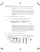
The ThunderLAN architecture expands the use of these two pins to allow the
attached PHY to interrupt the host using ThunderLAN. The clock cycle at the
end of a transaction on the MDIO signal is used to disable the PMI from driving
MDIO after a register read (the quiescent cycle). The interrupt is signaled to
the host on MDIO one clock cycle after this, for the half of the cycle when
MDCLK is high.
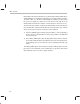
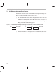
Figure 7–4. Assertion of Interrupt Waveform on the MDIO Line
MDCLK
Cycle
MDIO
D15 D16 QCYC MINT
QCYC = Quiescent
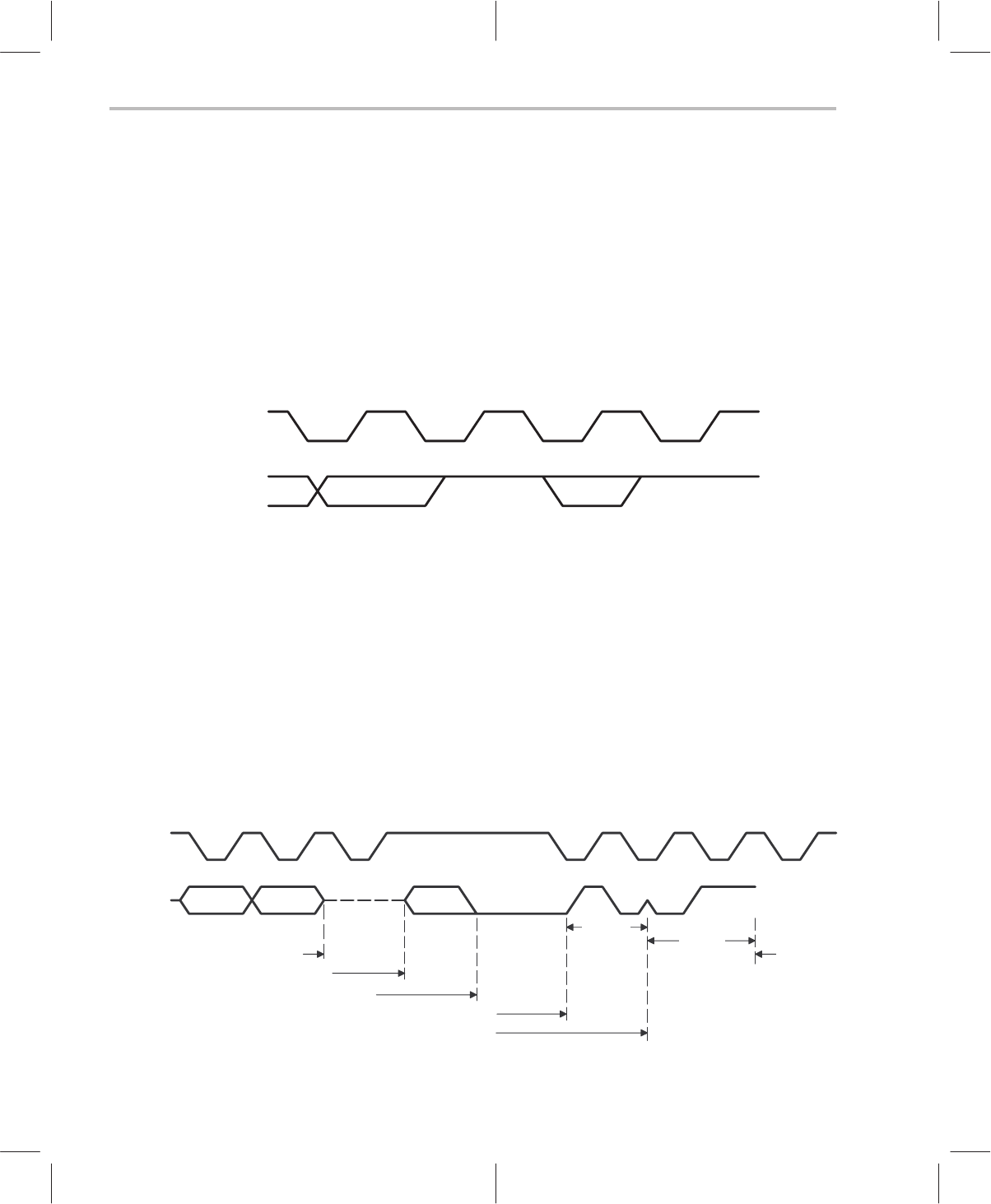
Since the Interrupt from the PHY is an open drain function, the PMI drives the
MDIO low prior to the falling edge that starts the start of frame (SOF) portion
of the management interface frame. During sync cycles the PHY releases the
interrupt on the MDIO to allow the management entity to pull the MDIO high
so a sync cycle is seen. In the diagram below, only one sync cycle is displayed,
but all 32 bits of the sync cycle are the same. On the ThunderLAN side of the
MII, a pullup is used to pull the MDIO signal high (no interrupt pending). The
value is such that the rising edge is less than 200 ns.
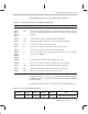
Figure 7–5. Waveform Showing Interrupt Between MII Frames
MDCLK
MDIO
Bit 1 Bit 0
End of transaction
Clear IntInHibit
Interrupt detected
Open collector off due to MDCLK seen low
New management transaction
Sync
SOF
R/W