
User Manual

Quick Start List for Stand-Alone
2-4
Quick Start
2.3 Quick Start List for Stand-Alone
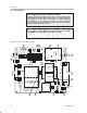
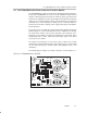
Follow these steps to use the TPA005D02 class D EVM stand-alone or to
connect it into existing circuits or equipment. Connections to the TPA005D02
module header pins can be made via individual sockets, wire-wrapping, or
soldering to the pins, either on the top or the bottom of the module circuit board.
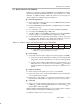
Power supply
1) Ensure that all external power sources are set to
OFF.
2) Connect an external regulated power supply set to 5 V to the module VDD
and GND pins taking care to observe marked polarity. Separate right
channel and left channel VDD supplies can be connected, or a single
supply can be used for both.
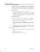
Inputs and outputs
3) Ensure that audio signal source level adjustments are set to minimum.
4) Connect the audio source to the module RIN+/RIN– and LIN+/LIN– pins,
taking care to observe marked polarity.
5) Connect a control signal to the module MUTE pin, if necessary. The control
signal should be high or floating for normal operation and low to mute the
module.
6) Connect a 4-Ω – 8-Ω speaker (use 4-Ω for best performance) to the
module ROUT+/ROUT– pins and another speaker to the LOUT+/LOUT–
pins, taking care to observe marked polarity.
Power-up
7) Verify correct voltage and input polarity and set the external power supply
to
ON.
The EVM should begin operation.
8) Adjust the signal source level as needed.