
User Manual

The TPA005D02 Audio Power Amplifier Evaluation Module
3-6
Details
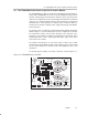
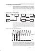
The H-bridge circuit consists of DMOS power transistors for supplying the
heavy currents which are required by the load. These transistors operate in
either the cutoff or saturation regions rather than the linear region in which
class AB amplifiers operate. Switching and conduction losses are reduced
since the transistor is active for only a small part of the duty cycle, reducing the
power dissipated by the power transistors and allowing more power to be
delivered to the load. A low pass filter (LPF) then removes the high frequency
switching component from the output signal, leaving an amplified version of
the original input signal. The DMOS transistors are arranged in an H-bridge
(full bridge) configuration to allow BTL operation, which further enhances the
amplifier performance.
3.2.2.1 BTL Operation
In the bridge-tied load output mode, the two output lines of each channel
operate as mirror images of each other for increased power. The speaker load
is connected directly across OUT+ and OUT–, and neither line is connected
to ground. BTL operation provides many benefits, including quadruple the
output power of single-ended operation and no need for bulky output coupling
capacitors. For more information, see the TPA005D02 amplifier IC data sheet,
TI Literature Number SLOS205.
To operate in the bridge-tied load output mode, the module output signal from
OUT+ must go through the speaker load and be returned directly to OUT–, and
NOT
to system ground. This requires that the OUT– line be isolated not only
from system ground, but also from the OUT– lines of any other amplifiers in
the system. The platform provides such isolated output lines from the amplifier
EVM sockets directly to separate left and right speaker connectors.