
User Manual

The TPA005D02 Audio Power Amplifier Evaluation Module
3-8
Details
3.2.3.2 Output Filter
Class D amplifiers require special filtering at the output to remove the
high-frequency switching component and accurately reconstruct the audio
signal. The output filter is a low-pass filter (LPF) which sets the high frequency
–3-dB point of the bandwidth. The major consideration here is how to choose
the components and set the desired –3-dB point.
Filter Design Goals
A second-order low-pass filter is used for the output filter. The Butterworth filter
is characterized by a flat response over the pass band and less attenuation
after the cutoff frequency. The order of the filter determines how many poles
exist that are at the same frequency, with each pole providing –20 dB per
decade of signal attenuation for a total of –40 dB per decade in this circuit. The
cutoff frequency (f
c)
can be determined using the equation
f
C
1
(2 LC
)
where L is the inductance and C is the equivalent capacitance. The values
used in the output filter are 15 µH for the inductor, and 0.22 µF and 1 µF
capacitors in parallel for an equivalent capacitance of 2.22 µF, setting the
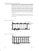
cutoff frequency to 27.5 kHz. The main purpose of this filter is to reduce the
switching frequency to an acceptable level and not attenuate the audio band.
The 250 kHz amplifier output signal is then reduced by –40 dB to one percent
of its pre-filter value.
The considerations for inductor selection are inductance, continuous and peak
current ratings, dc series resistance, and the packaging. The inductance was
chosen based on common inductance and capacitance values, to be 15 µH.
Class D Output Filter Design Methodology
The output filter attenuates the high switching frequency. A second-order
Butterworth low-pass filter was chosen for its flat pass band, good phase
response, and low parts count (it requires only an inductor and a capacitor).
The normalized transfer for the Butterworth filter is
H(s)
1
s
2
2
s 1
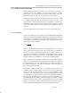
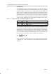
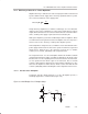
The next step is to realize the circuit and develop a transfer function. The filter
for a single-ended application is shown in Figure 3–6.
Figure 3–6. Single-Ended Class D Output FIlter
I
O
R
L
C
L
I
L
L
V
I
+
–
V
O
+
–