
User Manual

The TPA005D02 Audio Power Amplifier Evaluation Module
3-10
Details
The component equations adjusted for bridged amplifiers are
C
BTL
1
2
R
L
ω
0
L
BTL
2
R
L
2 ω
0
To find component values, let f
c
= 30 kHz, which yields ω
0
= 188495.6 radians/
second. If a 4-Ω speaker is used, R
L
= 4 Ω. This yields L
BTL
= 15 µH and C
BTL
= 0.94 µF. Additional capacitors can be added from each side of R
L
to ground
to provide a high-frequency short to ground. These additional capacitors
should be approximately 10% of 2C
BTL
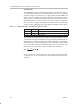
. The resulting output filter is shown in
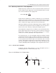
Figure 3–8 with the components rounded to standard values.
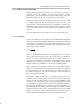
Figure 3–8. Resulting Bridged Output Filter
4 Ω
1 µF
0.22 µF
0.22 µF
15 µH
15 µH
LOUTP or ROUTP
LOUTN or ROUTN
Output Filter Components
The output inductors are key elements in the performance of the class D audio
amplifier system. It is important that these inductors have a high enough
current rating and a relatively constant inductance over frequency and
temperature. The current rating should be higher than the maximum current
expected to avoid magnetically saturating the inductor. When saturation
occurs, the inductor loses its functionality and looks like a short circuit to the
PWM signal, which increases the harmonic distortion considerably.
A shielded inductor may be required if the class D amplifier is placed in an EMI
sensitive system; however, the switching frequency is low for EMI
considerations and should not be an issue in most systems. The DC series
resistance of the inductor should be low to minimize losses due to power
dissipation in the inductor, which reduces the efficiency of the circuit.
Capacitors are important in attenuating the switching frequency and high
frequency noise, and in supplying some of the current to the load. It is best to
use capacitors with low equivalent-series-resistance (ESR). A low ESR
means that less power is dissipated in the capacitor as it shunts the
high-frequency signals. Ceramic (C24, C25, C26, and C27) and metal film
(C22 and C23) capacitors were selected because of their low ESR. Placing
these capacitors in parallel also parallels their ESR, effectively reducing the
overall ESR value. The voltage rating is also important, and, as a rule of thumb,
should be 2 to 3 times the maximum rms voltage expected to allow for high
peak voltages and transient spikes. These output filter capacitors should be
stable over temperature since large currents flow through them.