
User Manual

The TPA005D02 Audio Power Amplifier Evaluation Module
3-14
Details
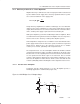
Fault Indicator
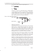
The TPA005D02 IC has two fault indicator pins (IC pins 41 and 42) to indicate
an under-voltage condition or a thermal fault. When the device is operating
normally, both pins are pulled up to the supply voltage through R6/D2 and
R7/D3. If the power supply voltage drops too low, the charge pump voltage
drops below the operational threshold and the low-side transistors short to
ground. When this occurs, IC pin 41 goes to ground, creating a voltage drop
across the LED, causing it to illuminate. The LED remains lit until the fault
circuit is reset by cycling the power or operating the shutdown or mute switch.
Table 3–1. TPA005D02 Class D EVM Fault Indicator Table
LED 1 LED 2 Fault Description
OFF OFF No faults—device is operating normally
OFF ON Under-voltage condition
ON ON Thermal fault
The fault indicator circuits (IC pins 41 and 42) are designed to minimize current
consumption and yet have an LED that is clearly visible when illuminated. The
LED should be as small as possible, have a wide viewing angle, and be bright
enough to clearly see while using minimal current. The LEDs selected require
a 2.1-V drop when activated, and approximately 3 mA of current to be fully
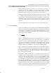
illuminated. The current-limit resistance needed is then calculated:
R
V
DD
–V
d
I
d
967
A 1-kΩ resistor was used for R6 and R7. Tests demonstrate that the LEDs
selected operate as expected and are clearly visible when the fault circuit is
activated.