
User Manual


Using The TPA005D02 Class D EVM Stand-Alone
3-28
Details
3.4 Using The TPA005D02 Class D EVM Stand-Alone
Using the TPA005D02 Class D Stereo Audio Power Amplifier Evaluation
Module stand-alone is much the same as using it with the platform. The same
4.5-V to 5.5-V power supply range and the isolated OUT+ and OUT– lines for
BTL operation requirement exists.
Power can be connected to either V
DD
pin on the module. The audio input
signal should be connected to the RIN+/RIN– and LIN+/LIN– module pins for
differential signals as shown below. Single-ended input signals are applied to
RIN+ and LIN+, while RIN– and LIN– are connected to ground.
Note that the mute signal applied to the EVM mute pin must be able to supply
enough current to overcome the pullup resistor on the module (100 kΩ).
Do not drive the module inputs unless speaker loads are connected to the
module outputs or the TPA005D02 amplifier IC will go into thermal shutdown.
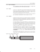
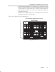
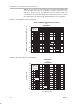
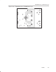
3.4.1 TPA005D02 Class D EVM Connected for BTL Output
Figure 3–21. TPA005D02 Class D EVM Connected for Stereo BTL Output
Audio
Input
(Right)
Audio
Input
(Left)
External Mute
Control
(active low)
Right
Left
5 V
Texas Instruments
1998
R6 R7
VDD
GND
L1
L2
L3
L4
U1
C21
C19
C15
+
TPA005D02 EVM Board Rev. A
VDD
GND
C25
Lout+
Lout–
Mute
Rout–
Rout+
C24
D2
D3
C4
C2
C3
C5
GND
RIN+
RIN–
C1
R2
R1
Q1
LIN–
LIN+
GND
Mute
S1
D1
C9
SLOP223
C7
C6
1
R3
+
C22
C23
C12
C10
C14
C13
C17
S2
C20
R4
R5
C8
C11
C27
C26
Shutdown