
Class D Stereo Audio Power Amplifier Module User's Guide TPA005D12

The TPA005D12 Class-D Audio Power Amplifier Evaluation Module
3-7
Details
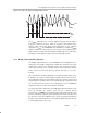
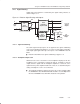
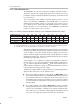
Figure 3–6. Class-D Input and Output Waveforms
V
DD
0 V
V
RAMP
V
IN
V
OUT
The V
RAMP
signal must be at a much higher frequency than the highest
frequency component of V
IN
to obtain an accurate representation at the
low-pass filter output and allow greater attenuation of the switching
component of V
OUT
. The TPA005D12 class-D EVM uses a 250 kHz V
RAMP
signal to sample V
IN
. This frequency is more than ten times higher than the
highest frequency component of the 20 Hz to 20 kHz range of the audio input,
providing excellent output resolution and easy filtering by the LPF.
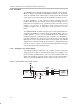
3.2.3 Bridge-Tied Load (BTL) Operation
The DMOS output transistors of the TPA005D12 class-D amplifier IC are
arranged in an H-bridge configuration to allow BTL operation. In the BTL
output mode, each half of the H-bridge operates 180° out of phase from the
other. The load, in this case, a speaker, is then connected between the two
halves, and is not connected directly to ground. The load is, in a sense,
floating.
BTL operation has two main advantages over single-ended operation. First,
it eliminates the need for a bulky output coupling capacitor to block any dc
offset voltage that may be present (which reduces the speaker response and
may damage the speaker). And second, it quadruples the output power that
can be delivered to the load. For more information, see the TPA005D12
amplifier IC data sheet, TI Literature Number SLOS240.
To operate in the BTL output mode, the EVM output signal from Rout+/Lout+
must go through the speaker load and be returned directly
to Rout–/Lout–, and
NOT
to system ground. This requires that the Rout–/Lout–
lines be isolated not only from system ground, but also from each other and
the out– lines of any other amplifiers in the system. The plug-n-play platform
provides such isolated output lines, connecting the EVM output pins directly
to left and right speaker connectors.