
Audio Power Amplifier User's Guide

Quick Start List for Stand-Alone
2-6
Quick Start
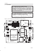
Evaluation Module Preparations
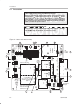
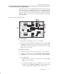
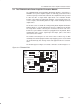
6) To have the module amplifier IC enter the shutdown mode when the
module mute control input is activated, set shutdown jumper S1 to
ON
. To
have the amplifier IC only mute when the module mute control input is
activated, set shutdown jumper S1 to
OFF
.
7) To select the line inputs, set input select jumper S3 to
OFF
. To select the
headphone inputs, set input select jumper S3 to
ON
.
8) To allow the module SE/BTL
control input to switch the amplifier IC
between single ended (SE) and bridge-tied load (BTL) output modes, set
output mode jumper S4 to
OFF
. To keep the module amplifier IC in the
single-ended output mode regardless of the control input state, set jumper
S4 to
ON
.
9) Set V
DD
bridge jumper S5 to
ON
to connect the RVDD and LVDD module
power input pins together, or to
OFF
to keep the two power inputs isolated
on board
10) To automatically select the headphone inputs when the single-ended
output mode is selected by the module SE/BTL
control input, set
autosense control jumper
S6
to
ON.
To isolate the amplifier IC input select
pin from the module output mode select control input, set autosense
control jumper
S6
to
OFF.
11) Set junction temperature measurement jumper S8 to
OFF
for normal
operation
Control Inputs
12) Connect control lines to the various module control input pins as needed:
a) HP/L*: A high selects the headphone input pins; a low or float selects
the line input pins.
b) SE/BTL*: A high selects the single-ended output mode; a low or float
selects the bridge-tied load output mode.
c) MUTE: A high mutes the amplifier IC on the module; a low or float
allows normal operation.
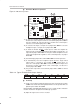
Power-up
13) Verify correct voltage and input polarity and set the external power supply
to
ON.
The EVM should begin operation.
14) Adjust the signal source level as needed.