
Datasheet

Quick Start List for Stand-Alone
2-6
Quick Start
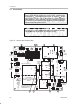
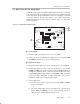
Evaluation module preparations
6) To allow the module SE/BTL control input to switch the amplifier IC
between single ended (SE) and bridge-tied load (BTL) output modes, set
output mode jumper S4 to
OFF
. To keep the module amplifier IC in the
single-ended output mode regardless of the control input state, set jumper
S4 to
ON
.
7) To allow the module HP/LINE control input to switch the amplifier IC
between using the HP pins and the LINE pins as the signal inputs, set the
input mode jumper S5 to
OFF
. To keep the amplifier IC in the HP input
mode regardless of the control input state, set jumper S5 to
ON
.
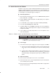
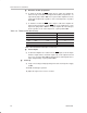
Table 2–6. TPA0212 EVM Gain Settings
S2 S3 OUTPUT MODE GAIN (V/V)
OFF OFF BTL 2
OFF ON BTL 6
ON OFF BTL 12
ON ON BTL 24
X X SE 1
Note: ON = Shunt installed, OFF = Open, X = Don’t care
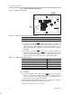
Control inputs
8) To allow the amplifier IC to switch from the LINE
inputs to the HP inputs
when the output switches from BTL output mode to SE output mode and
vice versa, set jumper S6 to
ON
. To allow the inputs and output modes to
switch independently, set jumper S6 to
OFF
.
Power-up
9) Verify correct voltage and input polarity and set the external power supply
to
ON.
The EVM should begin operation.
10) Adjust the signal source level as needed.