
Datasheet

1.2 TPA2054D4EVM Specifications
2 Operation
2.1 Quick Start for Stand-Alone Operation
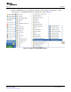
2.1.1 Software Installation Sequence
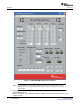
2.1.2 Evaluation Module Setup
Operation
www.ti.com
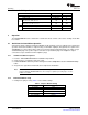
PARAMETER VALUE UNITS
V
DD
Supply voltage range –0.3 to 6 V
I
DD
Supply current 1.5 Maximum A
Speaker Continuous output power per channel,
1.25 W
8 Ω , V
DD
= 5 V, THD + N = 1%
P
O
Headphone Continuous output power per channel,
145 mW
16 Ω , V
DD
= 5 V, THD + N = 1%
Minimum load impedance (Speaker) 8 Ω
R
L
Minimum load impedance (Headphone) 16 Ω
The TPA2054D4EVM can be evaluated in a stand-alone mode or when connected to existing circuits with
I
2
C controls.
A desktop or laptop computer running the Windows™ XP operating system is required for the stand-alone
operation. Connect the EVM to a computer using a USB cable. A jumper (JP9) provides the option for the
TPA2054D4 to receive power from the USB or an external supply using banana plugs. The inputs accept
standard RCA plugs. The speaker output connection accepts banana plugs. The headphone output
connection accepts standard 3.5 mm headphone plugs.
1. Insert the TPA2054D4EVM Software Installation CD provided.
2. Unzip the files to a temporary folder onto a PC.
3. Install TPA2054D4 software by double-clicking the filename setup.exe located in TPA2054D4 Setup
folder.
4. Accept license agreement and defaults; then complete the installation.
Note: Uninstall the TPA2054D4 software at a later time using the Add/Remove Programs found
under the Windows Control Panel. It is unnecessary to repeat the preceding steps, once the
software is installed.
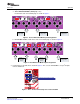
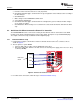
1. Configure the jumpers using Table 1 for the default settings:
Table 1. Jumpers Default Setting
Jumper Default Setting
JP1 (DVDD) Shunt
JP2, JP3 Shunt across each other
JP4 Shunt
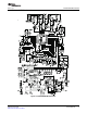
JP5, JP6, JP7, JP8 As shown in Figure 2
JP9 (USB PWR) Remove
TPA2054D4EVM 2 SLOU249 – April 2009
Submit Documentation Feedback