
Datasheet

Operation
www.ti.com
4. Ensure all external power sources are set to OFF.
5. Connect an external regulated power supply adjusted from 2.5 V to 5.5 V to the module VDD (J5) and
GND (J6) banana jacks, taking care to observe the marked polarity.
6. Install shunt in JP1 if DVDD is powered by the 1.8 V regulated supply from the EVM itself. If DVDD is
powered by another supply(between 1.8 V and 3.3 V), remove shunt in JP1 and connect the supply at
header 1 of JP1.
7. HPVDD is set to VDD by default. If HPVDD is powered by another supply (between 2.5 V and 5.5 V),
remove R17 and connect the supply at TP24.
8. Connect audio source as mentioned in step two.
9. Connect headphones to J4.
10. Connect speakers (8 Ω to 32 Ω ) to the output (J11, J12 for LOUT and J13, J14 for ROUT). The
speakers can also be connected to J2 and J3 if header connection is available in the speakers.
11. Plug in the USB.
12. Turn on power sources.
13. The TPA2054D4 can also be powered by USB cable if the audio amplifier output power is less than
100mW. Shunt JP9 and remove the power supply at J5 and J6 for USB power option.
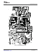
14. This table provides the test points information on the EVM:
Table 2. Test Points Information
Test Point Description
TP1, TP2, TP3, TP4 OUTR+, OUTR-, OUTL-, OUTL+
Filtered OUTR+, OUTR-, OUTL-,
TP5, TP6, TP7, TP8
OUTL+
TP9 HPVSS
TP10 INR_1
TP11 INL_1
TP12 INL_2
TP13 INR_2
T14 HPRIGHT
T15 HPLEFT
TP18 DVDD
TP20 SCL
TP23 SDA
TP24 HPVDD
TP27 VREF
TP19, TP21, TP22, TP25, TP26 GND
4 TPA2054D4EVM SLOU249 – April 2009
Submit Documentation Feedback