
Datasheet
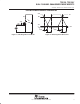

TPS1120, TPS1120Y
DUAL P-CHANNEL ENHANCEMENT-MODE MOSFETS
SLVS080A – MARCH 1994 – REVISED AUGUST 1995
3
POST OFFICE BOX 655303 • DALLAS, TEXAS 75265
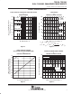
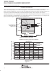
absolute maximum ratings over operating free-air temperature (unless otherwise noted)
†
UNIT
Drain-to-source voltage, V
DS
–15 V
Gate-to-source voltage, V
GS
2 or –15 V
V
GS
=27V
T
A
= 25°C ±0.39
V
GS
= –
2
.
7
V
T
A
= 125°C ±0.21
V
GS
=3V
T
A
= 25°C ±0.5
Continuous drain current each device (T
J
= 150
°
C) I
D
V
GS
= –
3
V
T
A
= 125°C ±0.25
A
Contin
u
o
u
s
drain
c
u
rrent
,
each
de
v
ice
(T
J
=
150°C)
,
I
D
V
GS
=45V
T
A
= 25°C ±0.74
A
V
GS
= –
4
.
5
V
T
A
= 125°C ±0.34
V
GS
=10V
T
A
= 25°C ±1.17
V
GS
= –
10
V
T
A
= 125°C ±0.53
Pulse drain current, I
D
T
A
= 25°C ±7 A
Continuous source current (diode conduction), I
S
T
A
= 25°C –1 A
Continuous total power dissipation See Dissipation Rating Table
Storage temperature range, T
stg
–55 to 150 °C
Operating junction temperature range, T
J
–40 to 150 °C
Operating free-air temperature range, T
A
–40 to 125 °C
Lead temperature 1,6 mm (1/16 inch) from case for 10 seconds 260 °C
†
Stresses beyond those listed under “absolute maximum ratings” may cause permanent damage to the device. These are stress ratings only, and
functional operation of the device at these or any other conditions beyond those indicated under “recommended operating conditions” is not
implied. Exposure to absolute-maximum-rated conditions for extended periods may affect device reliability.
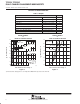
DISSIPATION RATING TABLE
PACKAGE
T
A
≤ 25°C
POWER RATING
DERATING FACTOR
‡
ABOVE T
A
= 25°C
T
A
= 70°C
POWER RATING
T
A
= 85°C
POWER RATING
T
A
= 125°C
POWER RATING
D 840 mW 6.71 mW/°C 538 mW 437 mW 169 mW
‡
Maximum values are calculated using a derating factor based on R
θJA
= 149°C/W for the package. These devices are
mounted on an FR4 board with no special thermal considerations.