
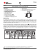
Datasheet

APPLICATION INFORMATION
2,3
5
4
6,7,8
POWER-SUPPLY CONSIDERATIONS
OVERCURRENT
OC RESPONSE
TPS2049
www.ti.com
......................................................................................................................................... SLVS713A – OCTOBER 2006 – REVISED SEPTEMBER 2007
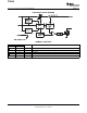
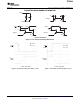
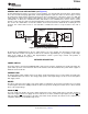
Figure 6. Typical Application
A 0.01- µ F to 0.1- µ F ceramic bypass capacitor between IN and GND, close to the device, is recommended.
Placing a high-value electrolytic capacitor on the output pin(s) is recommended when the output load is heavy.
This precaution reduces power-supply transients that may cause ringing on the input. Additionally, bypassing the
output with a 0.01- µ F to 0.1- µ F ceramic capacitor improves the immunity of the device to short-circuit transients.
A sense FET is employed to check for overcurrent conditions. Unlike current – sense resistors, sense FETs do not
increase the series resistance of the current path. When an overcurrent condition is detected, the device
maintains a constant output current and reduces the output voltage accordingly. Complete shutdown occurs only
if the fault is present long enough to activate thermal limiting.
Three possible overload conditions can occur. In the first condition, the output has been shorted before the
device is enabled or before VI(IN) has been applied (see Figure 6 ). The TPS2049 senses the short and
immediately switches into a constant-current output.
In the second condition, a short or an overload occurs while the device is enabled. At the instant the overload
occurs, very high currents may flow for a short period of time before the current-limit circuit can react. After the
current-limit circuit has tripped (reached the overcurrent trip threshold) the device switches into constant-current
mode.
In the third condition, the load has been gradually increased beyond the recommended operating current. The
current is permitted to rise until the current-limit threshold is reached or until the thermal limit of the device is
exceeded. The TPS2049 is capable of delivering current up to the current-limit threshold without damaging the
device. Once the threshold has been reached, the device switches into its constant-current mode.
The OC open-drain output is asserted (active low) when an overcurrent or overtemperature shutdown condition
is encountered after a 10-ms deglitch timeout. The output remains asserted until the overcurrent or
overtemperature condition is removed. Connecting a heavy capacitive load to an enabled device can cause a
momentary overcurrent condition; however, no false reporting on OC occurs due to the 10-ms deglitch circuit.
The TPS2049 is designed to eliminate false overcurrent reporting. The internal overcurrent deglitch eliminates
the need for external components to remove unwanted pulses. OC is not deglitched when the switch is turned off
due to an overtemperature shutdown.
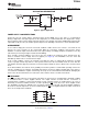
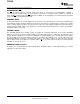
Figure 7. Typical Circuit for the OC Pin
Copyright © 2006 – 2007, Texas Instruments Incorporated Submit Documentation Feedback 7
Product Folder Link(s): TPS2049