
Datasheet


www.ti.com
3.3 Layout Considerations
4 EVM Setup
4.1 Recommended Test Equipment
4.2 Measuring Current Limit
EVM Setup
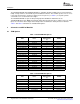
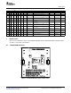
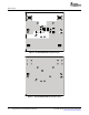
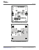
Figure 8. TPS20xxEVM-292 Bottom-Side Layout
The IN and OUT pins of U1 can carry significant current; so, traces to these pins should be of suitable
length and width to minimize the voltage drop to the load. Locate the 0.1- µ F bypass capacitors close to
the IN and OUT pins of U1.
The following test equipment is recommended:
• Two-channel storage oscilloscope
• Current probe
• Voltage probe
• 5 V at 5-A power supply
• Volt-ohm meter
• A passive or active load
The user should read the applicable data sheet before using the EVM.
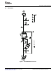
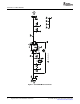
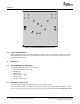
Figure 9 shows the EVM test set up for measuring current limit. The power distribution switch is enabled
into a short circuit for this measurement. Figure 10 shows the current waveform for TPS2051BEVM-290.
10 Single-Channel, Power-Distribution Switch EVM SLVU226B – October 2007 – Revised December 2007
Submit Documentation Feedback