
Datasheet

User's Guide
SLVU501A–August 2011– Revised January 2012
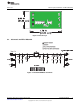
TPS2291xxEVM-656
This user's guide describes the characteristics, operation, and use of the TPS2291xxEVM-656 evaluation
module (EVM). This EVM demonstrates the Texas Instruments TPS2291xx load switch with controlled
turn on. The device contains a P-channel MOSFET that can operate over an input voltage of 1.4V to 5.5V.
The switch is controlled by an on/off input (ON), which is capable of interfacing directly with low-voltage
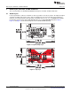
control signals. This user's guide includes setup instructions, schematic diagram, bill of materials, and
printed-circuit board layout drawings for the EVM.
1 Introduction
The TPS2291xxEVM-656 evaluation module (EVM) helps designers evaluate the operation and
performance of the TPS2291xx load switches. The board features the small 4-pin CSP package for a
small solution size.
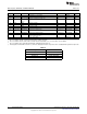
Table 1. TPS22910, TPS22912, TPS22913 Vout Rise Time, Enable, and Discharge
Options
Rise Time (µS) Enable Quick Output
EVM Device VIN(V)
Typ. (ON Pin) Discharge
HPA656-001 TPS22910A 0.5 5 Active Low No
HPA656-0011 TPS22912C 1000 5 Active High No
HPA656-0014 TPS22913B 100 5 Active High Yes
HPA656-0015 TPS22913C 1000 5 Active High Yes
1.1 Related Documentation From Texas Instruments
TPS2291xx, ULTRA-SMALL, LOW r
ON
LOAD SWITCH data sheet
1
SLVU501A–August 2011–Revised January 2012 TPS2291xxEVM-656
Submit Documentation Feedback
Copyright © 2011–2012, Texas Instruments Incorporated