
Datasheet

Setup
www.ti.com
2 Setup
This section describes the jumpers and connectors on the EVM as well as how to properly connect, set
up, and use the TPS2291xxEVM-656.
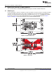
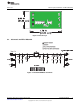
2.1 J1/J3 – Input Connections
This is the connection for the leads from the input source. Connect the positive connection to the VIN J1
and the negative connection to the GND J3.
2.2 J4/J6 – Output Connections
This is the connection for the output of the TPS2291xxEVM. Connect the positive connection of the load to
the VOUT J4 and the negative connection to the GND J6.
2.3 JP3 – ON
This is the enable input for the device. A shorting jumper must be installed on JP3 in either the HI or LO
positions. The TPS2291xx family contains products that are active high and active low (refer to Table 1).
ON must not be left unconnected. An external enable source can be applied to the EVM by removing the
shunt and connecting a signal to the center pin of JP3. Refer to the Datasheet for proper ON and OFF
voltage level settings. A switching signal may also be used and connected at this point.
2.4 J2/J5 – V
IN
Sense and V
OUT
Sense
These two connectors are used when very accurate measurements of input or output voltage are required.
Ron measurements should be made using these sense connections and measuring the voltage drop from
VIN to VOUT and then calculating the resistance.
2.5 JP1/JP2 – Input Capacitors
During normal operation a shorting jumper is placed on JP2 and connects C2 capacitor from the input of
the device to ground. JP1 and C1 may be used to connect a user selected capacitor value from the input
of the device to ground. Refer to the Applications Section of the Datasheet for additional information on
selecting the input capacitors.
2.6 JP4/JP5 – Output Capacitors
During normal operation a shorting jumper is placed on JP4 and connects C3 capacitor from the output of
the device to ground. JP5 and C4 may be used to connect a user selected capacitor value from the output
of the device to ground. Refer to the Applications Section of the Datasheet for additional information on
selecting the output capacitors.
2.7 JP6/JP7/JP8 – Output Resistors
During normal operation no shorting jumpers are placed on JP6, JP7, or JP8. A shorting jumper may be
used on JP6 to connect R1 load resistor from the output of the device to ground. JP7 and JP8 may be
used to connect R2 and R3 user selected load resistors from the output of the device to ground. R1, R2,
and R3 are intended for light loads of the output; observe the 1/8W power rating for these parts.
NOTE: R2 is populated on some EVM’s with a 14Ω 1/8W resistor, the maximum power rating for this
part can be easily exceeded, observe the power rating for R2 if it is populated and used on
your EVM.
2
TPS2291xxEVM-656 SLVU501A–August 2011–Revised January 2012
Submit Documentation Feedback
Copyright © 2011–2012, Texas Instruments Incorporated