
Datasheet
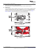
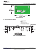
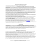

Board Layout, Schematic, and Bill of Materials
www.ti.com
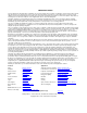
Table 2. Bill of Materials
(1) (2) (3) (4)
Count RefDes Value Description Size Part Number MFR
1 – PCB, 0.9 In x 1.7 In x 0.062 In HPA656 Any
1 C3 0.1 µF Capacitor, Ceramic,16-V, X7R, 10% 603 Std Std
1 C2 1 µF, use 10 µF Capacitor, Ceramic,6.3-V, X5R, 10% 603 Std Std
for A type
devices
0 C1, C4 OPEN Capacitor, Ceramic 603 Std Std
1 R1 560 Ω Resistor, 5% 1/8W 805 Std Std
1 R2 OPEN Resistor, 5% 1/8W 805 Std Std
0 R3 OPEN Resistor, 5% 1/8W 805 Std Std
13 J1 – J6, JP1–2, PEC02SAAN Header,2pin, 100mil spacing 0.100 inch x 2 PEC02SAAN Sullins
JP4–8
1 JP3 PEC03SAAN Header,3pin, 100mil spacing IC, 0.100 inch x 3 PEC03SAAN Sullins
1 U1 TPS2291xxYZP Single Chip, Low Input Voltage Current-Limited Load Switch YZV TPS2291xxYZV TI
V with Shut Off Auto-Restart
3 N/A N/A Shunt, 100-mil, Black 0.100 929950-00 3M
(1)
These assemblies are ESD sensitive, ESD precautions shall be observed.
(2)
These assemblies must be clean and free from flux and all contaminants. Use of no clean flux is not acceptable.
(3)
These assemblies must comply with workmanship standards IPC-A-610 Class 2.
(4)
Ref designators marked with an asterisk (**) cannot be substituted. All other components can be substituted with equivalent components.
Table 3.
Assembly number Text
HPA656-001 TPS22910AEVM-656
HPA656-011 TPS22912CEVM-656
HPA656-014 TPS22913BEVM-656
HPA656-015 TPS22913CEVM-656
6
TPS2291xxEVM-656 SLVU501A–August 2011–Revised January 2012
Submit Documentation Feedback
Copyright © 2011–2012, Texas Instruments Incorporated