TPS22921/22/22B Load Switch EVM User's Guide Literature Number: SLVU286 January 2009
SLVU286 – January 2009 Submit Documentation Feedback
Contents ................................................ 5 1 TPS22921/22/22B Load Switch Evaluation Module (EVM) 1.1 Introduction ................................................................................................................... 5 2 2.1 2.2 2.3 3 3.1 3.2 .................................................................................. 7 ................................................................................................................. 7 Schematic .....................
www.ti.com List of Figures 3-1 3-2 3-3 4-1 TPS22921/22/22B EVM Component Placement ........................................................................ 9 TPS22921/22/22B EVM Top-Side Layout .............................................................................. 10 TPS22921/22/22B EVM Bottom-Side Layout........................................................................... 10 EVM Setup For Calculating Voltage Drop and Load Current.........................................................
Chapter 1 SLVU286 – January 2009 TPS22921/22/22B Load Switch Evaluation Module (EVM) This user's guide describes the TPS22921/22/22B evaluation module (EVM). This guide contains the EVM schematics, bill of materials, assembly drawings, and top and bottom board layouts. 1.1 Introduction The TPS22921/22/22B EVM is an evaluation module for the Texas Instruments family of low-input voltage, ultra-low rON load switches. This EVM operates over a 0.9 V to 3.
TPS22921/22/22B Load Switch Evaluation Module (EVM) SLVU286 – January 2009 Submit Documentation Feedback
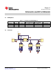
Chapter 2 SLVU286 – January 2009 Schematics and Bill of Materials 2.1 EVM Options Table 2-1. TPS22921/22/22B EVM Options 2.
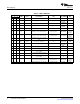
Bill of Materials 2.3 www.ti.com Bill of Materials Table 2.4. Bill of Materials QTY -01 -02 -03 1 1 1 REFDES VALUE DESCRIPTION SIZE MFR – – Two-layer, 2420 × 2320 mil, PCB 2420 × 2320 mil HPA393 Any STD 2 2 2 C1, C6 1 µF Capacitor, ceramic, 25 V, X5R 805 GRM216R61E1 05KA12D 1 1 1 C2 10 µF Capacitor, ceramic, 16 V, X5R 805 GRM21BR61C1 06KE15L STD 1 1 1 C5 0.
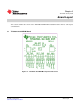
Chapter 3 SLVU286 – January 2009 Board Layout This section contains three views of the TPS22921/22/22B EVM evaluation board as well as some layout considerations. 3.1 TPS22921/22/22B EVM Board Figure 3-1.
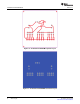
TPS22921/22/22B EVM Board www.ti.com Figure 3-2. TPS22921/22/22B EVM Top-Side Layout Figure 3-3.
www.ti.com 3.2 Layout Considerations Layout Considerations The VIN and VOUT pins of U1 can carry significant current; so, traces to these pins should be of suitable length and width to minimize voltage drop to the load. Locate the CIN and COUT bypass capacitors close to the VIN and VOUT pins of U1.
Board Layout SLVU286 – January 2009 Submit Documentation Feedback
Chapter 4 SLVU286 – January 2009 EVM Setup 4.1 Recommended Test Equipment The following test equipment is recommended: • Two-channel storage oscilloscope • Current probe • Voltage probe • 3.6 V at 2-A power supply • Volt-ohm meter 4.2 Calculating Voltage Drop and Load Current The user should read the applicable data sheet before using the EVM. Figure 4-1 shows the EVM test setup for measuring input and output voltage. The load switch is enabled into a passive on-board load for this measurement.
EVM Setup SLVU286 – January 2009 Submit Documentation Feedback
Chapter 5 SLVU286 – January 2009 Related Documentation from Texas Instruments • TPS22921, TPS22922, TPS22922B, Low-Input Voltage, Ultra-Low rON Load Switches data sheet (SLVS749) SLVU286 – January 2009 Submit Documentation Feedback Related Documentation from Texas Instruments 15
EVALUATION BOARD/KIT IMPORTANT NOTICE Texas Instruments (TI) provides the enclosed product(s) under the following conditions: This evaluation board/kit is intended for use for ENGINEERING DEVELOPMENT, DEMONSTRATION, OR EVALUATION PURPOSES ONLY and is not considered by TI to be a finished end-product fit for general consumer use. Persons handling the product(s) must have electronics training and observe good engineering practice standards.
IMPORTANT NOTICE Texas Instruments Incorporated and its subsidiaries (TI) reserve the right to make corrections, modifications, enhancements, improvements, and other changes to its products and services at any time and to discontinue any product or service without notice. Customers should obtain the latest relevant information before placing orders and should verify that such information is current and complete.