
Datasheet
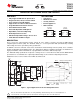
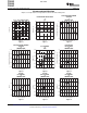

D−8 PW−8
1
FEATURES APPLICATIONS
1
2
3
4
5
6
7
8
VSS
CLASS UVLO
DET
RTN
PG
VDD
ILIM
1
2
3
4
5
6
7
8
VSS
CLASS N/C
DET
RTN
PG
VDD
ILIM
TPS2375/77
(TOP VIEW)
TPS2376
(TOP VIEW)
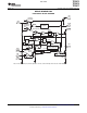
DESCRIPTION
TPS2375
SMAJ58A
Data to
Ethernet PHY
VDD
VSS
CLASS
DET
RTN
PG
Data to
Ethernet
PHY
1
3
6
4
5
7
8
TO DC/DC
CONVERTER
ILIM
2
RJ−45
DF01S
2 Places
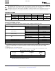
Note: Class 3 PD Depicted.
PG Pullup Resistor Is Optional.
TX
Pair
RX
Pair
Spare
Pair
Spare
Pair
V
DD
Input
Current
V
RTN
V
Detect Classify
Power Up & Inrush
Class 3
(PG-RTN)
100
kW
100 V
100 mF,
R
(DET)
24.9 kW,
1 %
R
(ILIM)
178 kW,
1 %
R
(ICLASS)
357 W,
1 %
100 V
0.1mF,
10 %
Note: All Voltages With Respect to VSS.
Current
data sheet
TPS2375
TPS2376
TPS2377
www.ti.com
............................................................................................................................................................ SLVS525B – APRIL 2004 – REVISED APRIL 2008
IEEE 802.3af PoE POWERED DEVICE CONTROLLERS
• VoIP Phones
• Fully Supports IEEE 802.3af Specification
• WLAN Access Points
• Integrated 0.58- Ω , 100-V, Low-Side Switch
• Security Cameras
• 15-kV System Level ESD Capable
• Internet Appliances
• Supports Use of Low-Cost Silicon Rectifiers
• POS Terminals
• Programmable Inrush Current Control
• Fixed 450-mA Current Limit
• Fixed and Adjustable UVLO Options
• Open-Drain, Power-Good Reporting
• Overtemperature Protection
• Industrial Temperature Range: -40 ° C to 85 ° C
• 8-Pin SOIC and TSSOP Packages
These easy-to-use 8-pin integrated circuits contain all of the features needed to develop an IEEE 802.3af
compliant powered device (PD). The TPS2375 family is a second generation PDC (PD Controller) featuring
100-V ratings and a true open-drain, power-good function.
In addition to the basic functions of detection, classification and undervoltage lockout (UVLO), these controllers
include an adjustable inrush limiting feature. The TPS2375 has 802.3af compliant UVLO limits, the TPS2377 has
legacy UVLO limits, and the TPS2376 has a programmable UVLO with a dedicated input pin.
The TPS2375 family specifications incorporate a voltage offset of 1.5 V between its limits and the IEEE 802.3af
specifications to accommodate the required input diode bridges used to make the PD polarity insensitive.
Additional resources can be found on the TI Web site www.ti.com.
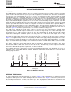
Figure 1. Typical Application Circuit and Startup Waveforms
1
Please be aware that an important notice concerning availability, standard warranty, and use in critical applications of
Texas Instruments semiconductor products and disclaimers thereto appears at the end of this data sheet.
PRODUCTION DATA information is current as of publication date.
Copyright © 2004 – 2008, Texas Instruments Incorporated
Products conform to specifications per the terms of the Texas
Instruments standard warranty. Production processing does not
necessarily include testing of all parameters.