Using the TPS2459EVM User's Guide Literature Number: SLUU349 March 2009
User's Guide SLUU349 – March 2009 TPS2459 Full-Featured AdvancedMC™ Slot Controller Evaluation Module 1 Introduction The Full-Featured AdvancedMC™ Slot Controller Evaluation Module (EVM) is a PCB platform for users to learn about the features and operation of the TPS2459 integrated circuit (IC) from Texas Instruments (TI). The TPS2459 Full Featured AdvancedMC™ Slot Controller manages a single 12-V and single 3.
Description www.ti.com 2.2 Typical Applications The TPS2459EVM contains the necessary input connectors and external components to demonstrate the application of 12-V and 3.3-V supplies to an AdvancedMC™-like load (12-V and 3.3-V load rails). The module can be used independantly with just the on-board load capacitance, or the user’s test loads can be attached to the output connectors. The EVM GUI provides easy access to the internal control bits to complete device configuration for the target application.
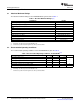
Electrical Specifications www.ti.com 3 Electrical Specifications 3.1 Absolute Maximum Ratings The absolute maximum ratings for the TPS2459EVM are given below in Table 1. Table 1. Absolute Maximum Ratings (1) (2) PARAMETER RATING Input voltage range, 12-V supply -0.3 V to 13.8 V Input voltage range, 3.3-V supply -0.3 V to 4 V Applied voltage, pins of J17, J18 -0.3 V to 5 V SUMx Applied voltage, pins of J17, J18 -0.3 V to 3.5 V SCL, SDA Output current, 12-V output 10A Output current, 3.
Electrical Specifications www.ti.com 3.3 Electrical Characteristics The electrical characteristics of the TPS2459EVM are as listed in Table 3. Table 3. Electrical Characteristics, TPS2459EVM (1) PARAMETER CONDITIONS Output voltage, payload power out (SLOT_PWR) ENx = OREN = HI, ILPWR < ILPWR_MAX Output voltage, mgmt power out (SLOT_MP) EN3 = HI, ILMP < ILMP_MAX MIN TYP MAX 10.8 13.2 3.135 3.465 UNITS V Current limit threshold, payload power 7.4 8.
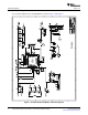
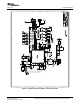
Schematic Diagram 4 www.ti.com Schematic Diagram + + 1 1 + + + + The schematic diagram for the TPS2459EVM is shown in Figure 1 and Figure 2. Figure 1.
Schematic Diagram + + + 1 3.3V @ 100mA 1 www.ti.com Figure 2.
Test Set-up www.ti.com 5 Test Set-up 5.1 Equipment Requirements The following test and interface equipment (not supplied) is required to verify EVM module operation, and begin using the EVM. • Power supply, 3.3 VDC, 500 mA minimum. • Power supply, 12 VDC, 10 A minimum. • Oscilloscope, 4 channel, with current probe. • Personal computer, running Windows OS (95/98/2000/NT/XP), with USB port.
Test Procedure www.ti.com 6 Test Procedure The following procedure can be used to verify functional operation of the EVM assembly upon receipt. 6.1 GUI Installation In an ATCA™ or µTCA™ application, the TPS2459 device may work in conjunction with an Intelligent Platform Management Controller (IPMC) device, which in turn is in communication with shelf management.
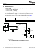
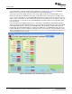
Test Procedure 6.3 www.ti.com Check-Out Steps If not already done, connect the EVM and test equipment as shown in Figure 3. Once the EVM USB PORT is connected to the PC, the green LED D51 on the EVM should illuminate. Turn on the 3.3-V power supply then turn on the 12.0-V supply. Verify all four STATUS LED’s are off. On the host PC, launch the EVM GUI from either the Start menu item or desktop icon. The GUI start-up screen of Figure 4 will appear.
Test Procedure www.ti.com On the oscilloscope, set the Channel 1 amplifier scale to 2 V/div, and the Channel 2 amplifier to 5 V/div. Position the Channel 1 trace a couple divisions down from the top of the scope screen, and position the Channel 2 trace about a division below it. Set the current probe amplifier scale to 50 mA/div, and position that trace towards the bottom of the scope screen. Set the scope to trigger on the rising edge of Channel 1, at a threshold of about 1.5 V.
Test Procedure www.ti.com Remove the current probe from the 3.3-V supply lead, and clamp it across the 12VIN supply lead. Change the Channel 4 amplifier scale to 2 A/div. Set the scope to trigger on Channel 2, and adjust the scope trigger threshold to about 3 V. In the GUI 12V CONTROL panel, click on the PASS FET button. In the STATUS panel, verify the 12V PASS FET, BLK FET, and OUT>PG Threshold indicators turn GREEN. On the EVM board, the PWR PGD green STATUS LED should be illuminated.
Test Procedure www.ti.com On the EVM board, set the PWR_OR enable slide switch to the DIS position. Use a DVM to verify the voltage at TP4 (SLOT_PWR), with respect to ground at TP6, drops to 11.4 0.6 V. Return the PWR_OR switch to the ENA position. After completing the above steps, the TPS2459 EVM GUI display should appear as shown in Figure 7. Note that all the STATUS indicators are green. Figure 7.
EVM Feature Details www.ti.com 7 EVM Feature Details 7.1 Test Points The TPS2459EVM contains numerous test points throughout the circuit for monitoring waveforms and voltage measurement. Table 6 lists the module test points and the signal available at each one. The EVM PCB layout connects all ground nodes and supply returns to a common GND node, via several power plane areas.
EVM Feature Details www.ti.com 7.2 Connecting Loads to the TPS2459EVM Both output power rails of the TPS2459EVM are supplied with some amount of load capacitance in the form of discrete electrolytics. The capacitors can be connected to or disconnected from their associated output nodes using 100-mil, 2-pin shunt jumpers across the on-board PCB headers.
EVM Feature Details 7.3 www.ti.com 2 I C Address Selection Three input pins on the TPS2459 are assigned for setting the device I2C address: A2, A1 and A0. These pins are tri-level inputs, allowing the device to be assigned any one of 27 unique address values. These pins can be tied to ground potential to generate a logic low (L), pulled up to the VINT pin to generate a logic high (H), or left open to float to a mid-range, no-connect (NC) level. On the EVM, address selection is performed using switch S4.
EVM Feature Details www.ti.com 7.4 Using the EVM GUI The TPS2459 EVM GUI comes packaged in an installer script/license agreement utility. Follow the instruction in Section 6.1 GUI Installation to Install the GUI to the target PC/laptop. 7.4.1 General GUI Information Once installed, and depending on the install options selected by the user, the GUI can be launced either from the TPS2459 EVM GUI program group in the Windows Start menu, or from the desk-top icon.
Assembly Drawing and PCB Layout 8 www.ti.com Assembly Drawing and PCB Layout The top assembly drawing and individual PCB layers for the TPS2459EVM are shown in Figure 8 through Figure 12. Figure 8.
Assembly Drawing and PCB Layout www.ti.com Figure 9.
Assembly Drawing and PCB Layout www.ti.com Figure 10.
Assembly Drawing and PCB Layout www.ti.com Figure 11.
Assembly Drawing and PCB Layout www.ti.com Figure 12.
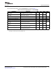
List of Materials www.ti.com 9 List of Materials Table 10. TPS2459EVM List of Materials (1) (2) (3) (4) (5) (6) (7) (8) (9) COUNT Std. 1 C11 Capacitor, aluminum, SM, 10V, 20%, 150 uF, Case D EEV-FK1A151P Panasonic 2 C4, C5 Capacitor, ceramic, 25V, X7R, 20%, 1 uF, 0805 Std. Std. 6 C51, C55, C56, Capacitor, ceramic, 25V, X7R, 20%, 0.1uF, 0603 C58, C60, C61 Std. Std. 2 C52, C53 Capacitor, ceramic, 50V, C0G, 10%, 22pF, 0603 Std. Std.
List of Materials www.ti.com Table 10.
List of Materials www.ti.com Table 10. TPS2459EVM List of Materials (continued) COUNT REF DES DESCRIPTION PART NUMBER MFR 5012 Keystone 15 TP1, TP2, TP4, Test point, white, 0.062 in. Hole, 5012, TH TP5, TP7, TP8, TP9, TP10, TP11, TP12, TP13, TP16, TP17, TP18, TP19 4 TP3, TP6, TP14, TP15 Test point, black, 0.062 in. hole, 5011, TH 5011 Keystone 1 U1 Full-Featured AdvancedMC Slot Controller, QFN-32 TPS2459RHB** Texas Instruments 1 U51 Serial EEPROM, 64K, 2.5-5.5V, 400 kHz Max.
EVALUATION BOARD/KIT IMPORTANT NOTICE Texas Instruments (TI) provides the enclosed product(s) under the following conditions: This evaluation board/kit is intended for use for ENGINEERING DEVELOPMENT, DEMONSTRATION, OR EVALUATION PURPOSES ONLY and is not considered by TI to be a finished end-product fit for general consumer use. Persons handling the product(s) must have electronics training and observe good engineering practice standards.
IMPORTANT NOTICE Texas Instruments Incorporated and its subsidiaries (TI) reserve the right to make corrections, modifications, enhancements, improvements, and other changes to its products and services at any time and to discontinue any product or service without notice. Customers should obtain the latest relevant information before placing orders and should verify that such information is current and complete.