
Datasheet
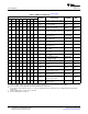

6 List of Materials
List of Materials
www.ti.com
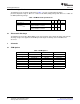
Table 3. EVM List of Materials
(1) (2) (3) (4) (5) (6)
QTY
PART
REF DES DESCRIPTION MFR
NUMBER
-001 -002 -003 -004 -005 -006 -007 -008
Capacitor, ceramic, 10 µ F, X7R, 10
1 1 1 1 1 1 1 1 C1 STD STD
V, 10%, 1206
Capacitor, ceramic, 16 V, X7R,
2 2 2 2 2 2 2 2 C2, C3 STD STD
10%, 0.1 µ F, 0805
Capacitor, tantalum, 150 µ F, 10 V, B45197A215
1 1 1 1 1 1 1 1 C4 KEMET
100 m Ω , 10%, 7343 (D) 7K409
Header, male 2 pin, 100-mil
1 1 1 1 1 1 1 1 J2 spacing, (36-pin strip), 0.100 inch x PTC36SAAN Sullins
2
Power-distribution switch, current
1 0 0 0 0 0 0 0 U1 TPS2552DBV TI
limited, SOT-23-6
Power-distribution switch, current
0 1 0 0 0 0 0 0 U1 TPS2553DBV
limited, SOT-23-6
Power-distribution switch, current TPS2552DBV
0 0 1 0 0 0 0 0 U1
limited, SOT-23-6 -1
Power-distribution switch, current TPS2553DBV
0 0 0 1 0 0 0 0 U1
limited, SOT-23-6 -1
Power-distribution switch, current TPS2552DR
0 0 0 0 1 0 0 0 U2 TI
limited, SON V
Power-distribution switch, current TPS2553DR
0 0 0 0 0 1 0 0 U2
limited, SON V
Power-distribution switch, current TPS2552DR
0 0 0 0 0 0 1 0 U2
limited, SON V-1
Power-distribution switch, TPS2553DR
0 0 0 0 0 0 0 1 U2
current-limited, SON V-1
PCB, 2.25 In x 2.225 In x 0.062 In,
1 1 1 1 1 1 1 1 -- HPA364 Any
SON
Resistor, chip, 1/10 W, 1%, 10.0 CRCW0805-
2 2 2 2 2 2 2 2 R1, R2 Vishay
k Ω , 0805 1002F
Resistor, chip, 1/10 W, 1%, 20.0 CRCW0805-
2 2 2 2 2 2 2 2 R3, R4 Vishay
k Ω , 0805 2002-F
Switch, SPDT, slide, PC mount,
1 1 1 1 1 1 1 1 S1 09-03201-02 EAO
500 mA, 0.400 x 0.100 in
Terminal block, 2 pin, 6 A, 3.5 mm,
2 2 2 2 2 2 2 2 J1, J3 ED555/2DS OST
0.27 x 0.25 inch
TP1, TP2,
Test point, white, thru-hole color
5 5 5 5 5 5 5 5 TP3, TP4, 5002 Keystone
keyed, 0.100 x 0.100 in
TP5
TP6, TP7, Test point, SM, 0.150 x 0.090,
4 4 4 4 4 4 4 4 5016 Keystone
TP8, TP9 0.185 x 0.135 in
(1)
These assemblies are ESD sensitive, ESD precautions shall be observed.
(2)
These assemblies must be clean and free from flux and all contaminants. Use of no clean flux is not acceptable.
(3)
These assemblies must comply with workmanship standards IPC-A-610 Class 2.
(4)
Ref designators marked with an asterisk ('**') cannot be substituted. All other components can be substituted with equivalent MFG's
components.
(5)
Attach a rubber bumper to each corner of the PCB.
(6)
Insert shorting jumper on header J2.
10 TPS2552/3, Power-Distribution Switch SLUU339 – December 2008
With Adjustable Current-Limit EVM
Submit Documentation Feedback