
Datasheet

4 EVM Setup
4.1 Recommended Test Equipment
4.2 Measuring the Short-Circuit Output Current-Limit
5V, 5A
0-W
+
IN
-
+
OUT
-
EVM
Oscilloscope
Current
Probe
FAULT
VoltageProbe
7" TwistedPair,#20AWG
EVM Setup
www.ti.com
The following test equipment is recommended:
• Two-channel storage oscilloscope
• Current probe
• Voltage probe
• An adjustable power supply with a 2.5-V to 6.5-V output and a 10-A output current-limit
• Volt-ohm meter
• A passive or active load capable of handling 3 A.
The user should read the TPS2552/3 data sheet before using the EVM.
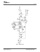
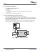
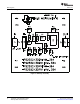
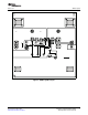
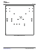
Figure 2 shows the EVM test setup for measuring current-limit. Switch S1 enables the power-distribution
switch into a short circuit for this measurement. For retry controllers, Figure 3 shows the current waveform
for the TPS2552/3DRVEVM with a shorting jumper populating header J2; Figure 4 shows the current
waveform with header J2 unpopulated.
For latch-off controllers Fig5 shows the current waveform for the TPS2552/3DRV EVM with a shorting
jumper populating header J2; Figure 6 shows the current waveform with header J2 unpopulated.
Figure 2. EVM Setup For Measuring Current-Limit
4 TPS2552/3, Power-Distribution Switch SLUU339 – December 2008
With Adjustable Current-Limit EVM
Submit Documentation Feedback