Using the TPS2556EVM-423 and TPS2557EVM-423 User's Guide Literature Number: SLUU393 November 2009
User's Guide SLUU393 – November 2009 Using the TPS2556EVM-423 and TPS2557EVM-423 This user’s guide describes the TPS2556EVM-423 and TPS2557EVM-423 evaluation modules (EVM). This guide contains the EVM schematic, list of materials, assembly drawing, and top and bottom board layouts. 1 Introduction The TPS2556EVM-423 and TPS2557EVM-423 are evaluation modules (EVM) for Texas Instruments’ power-distribution switches with adjustable current-limit. These EVMs operate over a 2.5-V to 6.5-V range.
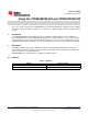
Description www.ti.com 2.2 Jumpers Table 2. Jumpers 2.3 CURRENT J2 0.1 A ON 1.0 A OFF Test Points Table 3.
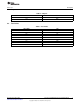
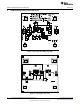
Schematic Schematic + + 3 www.ti.com Figure 1.
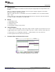
Getting Started www.ti.com 4 Getting Started Preset the power supply to 5 V and turn off. Connect the power supply output to the input terminals of the HPA423. Slide S1 to disable the TPS2556 or TPS2557. Turn on the power supply to apply 5.0 V to the EVM input-power terminals. VOUT should be 0 V. Slide S1 to enable the device. For TPS2556, set S1 to LO; for TPS2557, set S1 to HI. VOUT should be VIN + / - 0.3 V. Set the oscilloscope to auto trigger mode and the horizontal-sweep to 4 ms/div.
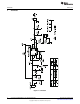
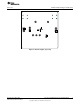
EVM Assembly Drawing and PCB Layout 6 www.ti.com EVM Assembly Drawing and PCB Layout Figure 3. Top Layer Assembly (top view) Figure 4.
EVM Assembly Drawing and PCB Layout www.ti.com Figure 5.
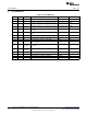
List of Materials 7 www.ti.com List of Materials Table 4. List of Materials 8 -002 -001 REF DES DESCRIPTION PART NUMBER MFR 1 1 C1 Capacitor, ceramic, X7R, 10 V, 10%, 10 µF, 1206 STD STD 2 2 C2, C3 Capacitor, ceramic, 16 V, X7R, 10%, 0.1 µF, 0805 STD STD C4 Capacitor, tantalum, 10 V, 100 mΩ, 10%, 150 µF, 7343 (D) B45197A2157K409 KEMET C5 Capacitor, tantalum, 10 V, 100 mΩ, 10%, 150 µF, 7343 (D) B45197A2157K409 KEMET J1, J3 Terminal block, 2 pin, 6 A, 3.5 mm, 0.27 inch x 0.
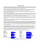
List of Materials www.ti.com EVALUATION BOARD/KIT IMPORTANT NOTICE Texas Instruments (TI) provides the enclosed product(s) under the following conditions: This evaluation board/kit is intended for use for ENGINEERING DEVELOPMENT, DEMONSTRATION, OR EVALUATION PURPOSES ONLY and is not considered by TI to be a finished end-product fit for general consumer use. Persons handling the product(s) must have electronics training and observe good engineering practice standards.
IMPORTANT NOTICE Texas Instruments Incorporated and its subsidiaries (TI) reserve the right to make corrections, modifications, enhancements, improvements, and other changes to its products and services at any time and to discontinue any product or service without notice. Customers should obtain the latest relevant information before placing orders and should verify that such information is current and complete.