
Datasheet


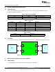
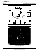
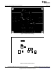

Table Of Contents
DUT
TPS25910EVM-088
J1
J2
Power
Supply
Load
J3
J4
±
+
±
+
±
+
+
±
General Configuration and Description
www.ti.com
4 General Configuration and Description
4.1 Physical Access
Table 1 lists the EVM connector functionality, Table 2 describes the test point availability and Table 3
describes the jumper functionality.
Table 1. Connector Functionality
Connector Label Description
J1/J2 VIN/GND 3 V–20 V input to the EVM
J3/J4 VOUT/GND 3 V–20 V output from the EVM
Table 2. Test Points
Test Point Color Label Description
TP1/TP10 WHT/WHT VIN/GND 3 V–20 V input to the EVM
TP4/TP8/TP9 WHT/WHT/WHT VOUT/GND/GND 3 V–20 V output from the EVM
TP2 WHT EN Active-low ENABLE input
TP3 WHT OUT Output from TPS25910
TP5 WHT GATE GATE output for slew rate control
TP6 WHT FLT Active low fault output
Table 3. Jumper
Jumper Label Description
J5 J5 Install shunt for slew rate control
4.2 Test Setup
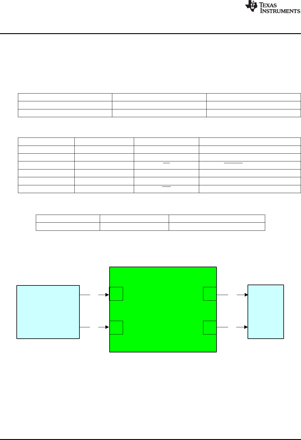
Figure 2 shows a typical test setup for the EVM. Connect J1/J2 to the power supply and J3/J4 to the load.
Figure 2. Typical TPS25910EVM-088 Test Setup
5 EVM Assembly Drawings and Layout Guidelines
5.1 PCB Drawings
The following figures show component placement and layout of the EVM.
4
TPS25910EVM-088 EVM: Evaluation Module for the TPS25910 SLVU760A–August 2012–Revised January 2013
Submit Documentation Feedback
Copyright © 2012–2013, Texas Instruments Incorporated