
Datasheet

SLVS224B − NOVEMBER 1999 − REVISED AUGUST 2002
1
POST OFFICE BOX 655303 • DALLAS, TEXAS 75265
D Floating Bootstrap or Ground-Reference
High-Side Driver
D Adaptive Dead-Time Control
D 50-ns Max Rise/Fall Times With 3.3-nF Load
D 2.4-A Typical Output Current
D 4.5-V to 15-V Supply Voltage Range
D TTL-Compatible Inputs
D Internal Schottky Bootstrap Diode
D Low Supply Current....3 mA Typical
D Ideal for High-Current Single or Multiphase
Power Supplies
D −40°C to 125°C Operating Virtual
Junction-Temperature Range
description
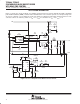
The TPS2836 and TPS2837 are MOSFET drivers for synchronous-buck power stages. These devices are ideal
for designing a high-performance power supply using switching controllers that do not have MOSFET drivers.
The drivers are designed to deliver minimum 2-A peak currents into large capacitive loads. The high-side driver
can be configured as ground-reference or as floating-bootstrap. An adaptive dead-time control circuit eliminates
shoot-through currents through the main power FETs during switching transitions and provides high efficiency
for the buck regulator.
The TPS2836 has a noninverting input, while the TPS2837 has an inverting input. These drivers, available in
8-terminal SOIC packages, operate over a junction temperature range of − 40°C to 125°C.
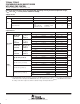
AVAILABLE OPTIONS
PACKAGED DEVICES
T
J
SOIC
(D)
−40°C to 125°C
TPS2836D
TPS2837D
The D package is available taped and reeled. Add R
suffix to device type (e.g., TPS2836DR)
Related Synchronous MOS FET Drivers
DEVICE NAME ADDITIONAL FEATURES INPUTS
TPS2830
ENABLE, SYNC and CROWBAR
CMOS
Noninverted
TPS2831
ENABLE, SYNC and CROWBAR CMOS
Inverted
TPS2832
W/O ENABLE, SYNC and CROWBAR
CMOS
Noninverted
TPS2833
W/O ENABLE, SYNC and CROWBAR CMOS
Inverted
TPS2834
ENABLE, SYNC and CROWBAR
TTL
Noninverted
TPS2835
ENABLE, SYNC and CROWBAR TTL
Inverted
Copyright 2002, Texas Instruments Incorporated
!"#$%! & '("")% $& ! *(+,'$%! -$%).
"!-('%& '!!"# %! &*)''$%!& *)" %/) %)"#& ! )0$& &%"(#)%&
&%$-$"- 1$""$%2. "!-('%! *"!')&&3 -!)& !% )')&&$",2 ',(-)
%)&%3 ! $,, *$"$#)%)"&.
Please be aware that an important notice concerning availability, standard warranty, and use in critical applications of
Texas Instruments semiconductor products and disclaimers thereto appears at the end of this data sheet.
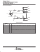
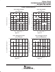
D PACKAGE
(TOP VIEW)
1
2
3
4
8
7
6
5
IN
PGND
DT
V
CC
BOOT
HIGHDR
BOOTLO
LOWDR