
Datasheet


SLUU189 − July 2004
6
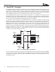
TPS40009-Based 5-A Converter in Less Than One Square Inch
4 Design Procedure
4.1 Controller Selection
The TPS40009 synchronous buck controller is selected for this small size application because the 600-kHz
switching frequency enables the selection of minimally sized filter components. The TPS40007 is available for
applications needing 300-kHz operation for designs where efficiency is to be optimized.
4.2 Inductance Value
The output inductor value is selected to set the ripple current to a value most suited to overall circuit functionality.
The inductor value is calculated in equation (1).
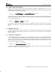
L +
V
OUT
f I
RIPPLE
ȧ
ȡ
Ȣ
1 *
V
OUT
V
IN(max)
ȧ
ȣ
Ȥ
+
1.2 V
600 kHz 1.25 A
ǒ
1 *
1.2 V
3.6 V
Ǔ
+ 1.07 mH
where I
RIPPLE
is chosen to be 25% of I
OUT
, or 1.25 A. A common value of 1 µH is selected.
4.3 Input Capacitor Selection
Bulk input capacitor selection is based on allowable input voltage ripple and required RMS current carrying
capability. In typical buck converter applications, the converter is fed from an upstream power converter with
its own output capacitance. In this converter, onboard capacitance is provided to supply the current required
during the top MOSFET on-time while keeping ripple within acceptable limits. For this power level, input voltage
ripple of 150 mV is reasonable, and a conservative minimum value of capacitance is calculated in equation (2).
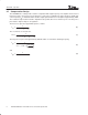
C +
I Dt
DV
+
5A 606 ns
0.15 V
+ 20 mF
To meet this requirement with the lowest size and cost, a single 22 µF, X5R ceramic capacitor might be
considered. Although these capacitors have an extremely small resistance a typical datasheet indicates that
the part undergoes a 30°C temperature rise with 2 A
RMS
current at 500 kHz. With V
IN
= 3.0 V our circuit requires
nearly 2 A
RMS
of current, so for a conservative design two capacitors are selected to allow for conservative
current derating. These capacitors function as power bypass components and should be located near the
MOSFET package, to keep the high frequency current flow in a tight loop. The low impedance characteristics
of the dual ceramic capacitors help to reduce noise on the V
DD
supply of the device. Specifically, the high side
MOSFET current sense is referenced to this point, so noise at the device must be kept to a low level.
(1)
(2)