
Datasheet

SLUU195A − June 2004 − Revised January 2005
17
TPS40090 Multi-Phase Buck Converter and TPS2834 Drivers Steps-Down from 12-V to 1.5-V at 100 A
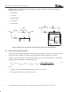
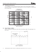
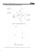
6.4 Transient Response
The on-board load transient circuit enables to check the step load transient response on the
same board. Simply by putting a jumper to connect Pin1 and 2 of J3, a 90-A step load is created
by three 50-mΩ resistors placed on the board. The slew rates of the transient are 200 A/µs for
the load step-down and 160 A/µs for the load step-up.
The transient response is shown in Figure 6 as the load is stepped from 10 to 100 A. The output
deviation is approximately 200 mV and the settling time is within 15 µs.
Load Step = 90 A
t − Time − 20 µs / div
Something Voltage
(10 mV/div)
Something Voltage
(10 mV/div)
Figure 12. Transient Response