
User's Guide Converter TPS40009EVM-002


SLUU195 − June 2004
4
TPS40090 Multi-Phase Buck Converter and TPS2834 Drivers Steps-Down from 12-V to 1.5-V at 100 A
TPS40090 Multi-Phase Buck Converter and TPS2834
Drivers Steps-Down from 12-V to 1.5-V at 100 A
Systems Powe
r
Contents
1 Introduction 4. . . . . . . . . . . . . . . . . . . . . . . . . . . . . . . . . . . . . . . . . . . . . . . . . . . . . . . . . . . . . . . . . . . . . . . . .
2 Features 5. . . . . . . . . . . . . . . . . . . . . . . . . . . . . . . . . . . . . . . . . . . . . . . . . . . . . . . . . . . . . . . . . . . . . . . . . . . .
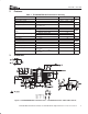
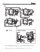
3 Schematic 5. . . . . . . . . . . . . . . . . . . . . . . . . . . . . . . . . . . . . . . . . . . . . . . . . . . . . . . . . . . . . . . . . . . . . . . . . . .
4 Component Selection 7. . . . . . . . . . . . . . . . . . . . . . . . . . . . . . . . . . . . . . . . . . . . . . . . . . . . . . . . . . . . . . . .
5 Test Setup 14. . . . . . . . . . . . . . . . . . . . . . . . . . . . . . . . . . . . . . . . . . . . . . . . . . . . . . . . . . . . . . . . . . . . . . . . .
6 Test Results/Performance Data 15. . . . . . . . . . . . . . . . . . . . . . . . . . . . . . . . . . . . . . . . . . . . . . . . . . . . . .
7 Layout Considerations 19. . . . . . . . . . . . . . . . . . . . . . . . . . . . . . . . . . . . . . . . . . . . . . . . . . . . . . . . . . . . . .
8 EVM Assembly Drawing and PCB Layout 20. . . . . . . . . . . . . . . . . . . . . . . . . . . . . . . . . . . . . . . . . . . . .
9 List of Materials 24. . . . . . . . . . . . . . . . . . . . . . . . . . . . . . . . . . . . . . . . . . . . . . . . . . . . . . . . . . . . . . . . . . . .
1 Introduction
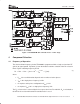
The TPS40090EVM−002 multi-phase dc-to-dc converter utilizes the TPS40090 multi-phase
controller and TPS2834 adaptive driver to step down a 12-V input to 1.5-V at 420 kHz. The
output current can exceed 100 A. The TPS40090 provides fixed-frequency, peak current-mode
control with forced-phase current balancing. Phase currents are sensed by the voltage drop
across the DC resistance (DCR) of inductors. Other features include a single voltage operation,
true differential output voltage sense, user programmable current limit, capacitor-programmable
soft-start and a power good indicator. Device operation is specified in the TPS40090
datasheet
[1]
.
TPS40090EVM-002 can be configured into 2-, 3− or 4-phase operation. For 2-phase operation,
populate R65 and R66 to tie PWM2 and PWM4 up to internal 5-V and leave components in
related phases unpopulated. For 3-phase operation, tie PWM4 to BP5 through R66 only. For
4-phase operation, leave both R65 and R66 unpopulated.
In this user’s guide, all the tests are conducted under 4 phase operation.