
Datasheet


PW RHD
1
2
3
4
5
6
7
8
9
10
11
12
24
23
22
21
20
19
18
17
16
15
14
13
CS1
CS2
CS3
CS4
CSCN
ILIM
DROOP
REF
COMP
FB
DIFFO
VOUT
EN/SYNC
VIN
BP5
PWM1
PWM2
PWM3
PWM4
GND
RT
SS
PGOOD
GNDS
FB
DIFFO
VOUT
NC
GNDS
PGOOD
NC
28
CS2
27
CS1
26
NC
25
NC
24
EN/SYNC
23
VIN
22
BP5
CS3
CS4
CSCN
ILIM
DROOP
REF
COMP
PWM1
PWM2
PWM3
PWM4
GND
RT
SS
8
9
10
11
12
13
14
21
20
19
18
17
16
15
1
2
3
4
5
6
7
TPS40090
TPS40091
www.ti.com
SLUS578B –OCTOBER 2003– REVISED MAY 2006
HIGH-FREQUENCY, MULTIPHASE CONTROLLER
Check for Samples: TPS40090, TPS40091
1
FEATURES
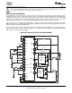
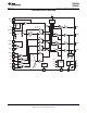
PW PACKAGE
2
• Two-, Three-, or Four-Phase Operation
(TOP VIEW)
• 5-V to 15-V Operating Range
• Programmable Switching Frequency Up to
1-MHz/Phase
• Current Mode Control With Forced Current
Sharing
(1)
(1)
Patent pending.
• 1% Internal 0.7-V Reference
• Resistive Divider Set Output Voltage
• True Remote Sensing Differential Amplifier
• Resistive or DCR Current Sensing
• Current Sense Fault Protection
RHD PACKAGE
• Programmable Load Line
(BOTTOM VIEW)
• Compatible with UCC37222 Predictive Gate
Drive™ Technology Drivers
• 24-Pin Space-Saving TSSOP Package
• 28-Pin QFN Package
• TPS40090: Binary Outputs
• TPS40091: 3-State Outputs
APPLICATIONS
• Internet Servers
• Network Equipment
• Telecommunications Equipment
• DC Power Distributed Systems
DESCRIPTION
The TPS4009x is a two-, three-, or four-phase programmable synchronous buck controller that is optimized for
low-voltage, high-current applications powered by a 5-V to 15-V distributed supply. A multi-phase converter offers
several advantages over a single power stage including lower current ripple on the input and output capacitors,
faster transient response to load steps, improved power handling capabilities, and higher system efficiency.
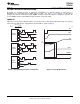
Each phase can be operated at a switching frequency up to 1-MHz, resulting in an effective ripple frequency of
up to 4-MHz at the input and the output in a four-phase application. A two-phase design operates 180 degrees
out-of-phase, a three-phase design operates 120 degrees out-of-phase, and a four-phase design operates 90
degrees out-of-phase as shown in Figure 1.
The number of phases is programmed by connecting the de-activated phase PWM output to the output of the
internal 5-V LDO. In two-phase operation the even phase outputs should be de-activated.
1
Please be aware that an important notice concerning availability, standard warranty, and use in critical applications of Texas
Instruments semiconductor products and disclaimers thereto appears at the end of this data sheet.
2Predictive Gate Drive is a trademark of Texas Instruments.
PRODUCTION DATA information is current as of publication date.
Copyright © 2003–2006, Texas Instruments Incorporated
Products conform to specifications per the terms of the Texas
Instruments standard warranty. Production processing does not
necessarily include testing of all parameters.