
Datasheet

User's Guide
SLVU198A – February 2007 – Revised May 2007
Using the TPS40131EVM, A 40A Single Output
Two-Phase Synchronous Buck Converter
Contents
1 Introduction .......................................................................................... 2
2 Description ........................................................................................... 2
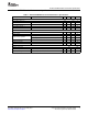
3 TPS40131EVM Electrical Performance Specifications ........................................ 3
4 Schematic ........................................................................................... 4
5 Test Set Up .......................................................................................... 5
6 TPS40131EVM Typical Performance Data and Characteristic Curves .................... 10
7 EVM Assembly Drawings and Layout .......................................................... 13
8 List of Materials .................................................................................... 19
List of Figures
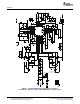
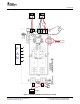
1 TPS40131EVM Power Stage/Control Schematic For Reference Only, See Table 3:
Bill of Materials for Specific Values .............................................................. 4
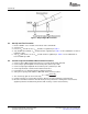
2 TPS40131EVM Recommended Test Set-Up ................................................... 7
3 Output Ripple Measurement ...................................................................... 8
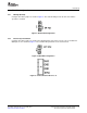
4 Default EN Configuration .......................................................................... 9
5 EN/SYNC Configuration ........................................................................... 9
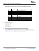
6 Connect External Clock to J2 ..................................................................... 9
7 TPS40131EVM Efficiency V
IN
= 10.8–13.2V, V
OUT
= 1.5V, I
OUT
= 0–40A ................. 11
8 TPS40131EVM V
OUT
= 1.5V Load Regulation ................................................ 11
9 TPS40131EVM V V
OUT
= 1.5V Line Regulation ............................................... 12
10 Loop Gain When V
IN
= 13.2V and I
OUT
= 40A ................................................. 12
11 0–15A load step, Ch1: I
OUT
; Ch4: V
OUT
........................................................ 13
12 TPS40131EVM Component Placement (Viewed from Top) ................................ 14
13 TPS40131EVM Top Copper (Viewed from Top) .............................................. 15
14 TPS40131EVM Layer 2 Copper (X-Ray View from Top) .................................... 16
15 TPS40131EVM Layer 3 Copper (X-Ray View from Top) .................................... 17
16 TPS40131EVM Bottom Copper (X-Ray View from Top) ..................................... 18
List of Tables
1 TPS40131EVM Electrical and Performance Specifications ................................... 3
2 List of Test Points ................................................................................. 10
3 TPS40131EVM Bill of Materials ................................................................. 19
SLVU198A – February 2007 – Revised May 2007 Using the TPS40131EVM, A 40A Single Output 1
Two-Phase Synchronous Buck Converter
Submit Documentation Feedback